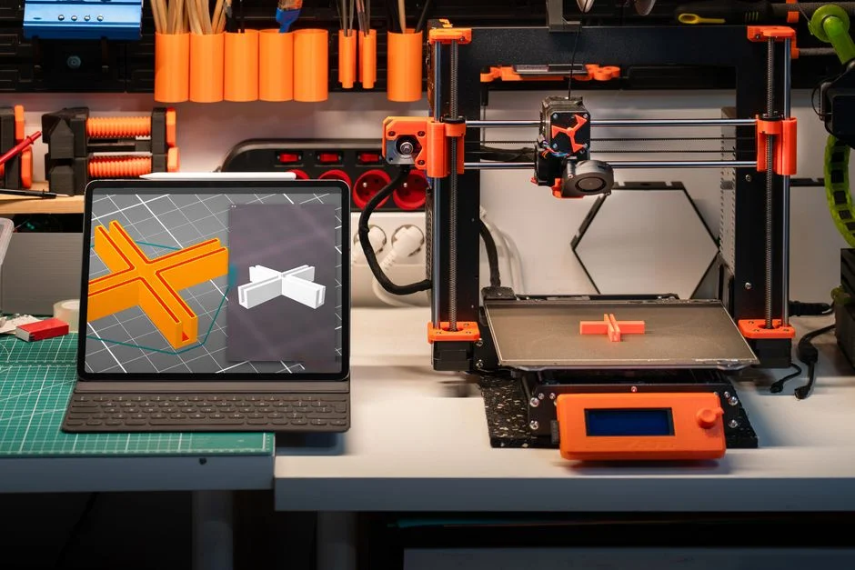
Tinkercad 3D design is often the quickest way to move from an idea in your head to a printable, shareable, or editable model on your screen, especially when you want results without wrestling with complex interfaces. The environment is browser-based, so setup is minimal, and the learning curve feels approachable even if you have never opened a CAD program before. Yet the simplicity is not a limitation; it is a deliberate focus on core modeling actions—placing shapes, resizing, aligning, grouping, and refining—so you can build useful objects fast. That combination makes it popular in classrooms, maker spaces, and home workshops where time matters and the goal is to prototype, iterate, and learn through doing. When you open the workspace, the grid and ruler give immediate scale context, and the camera controls help you understand depth and orientation. Those fundamentals are enough to create keychains, enclosures, brackets, organizers, miniatures, and basic mechanical parts, as well as visual mockups for later refinement in advanced CAD tools.
Table of Contents
- My Personal Experience
- Getting Started with Tinkercad 3D Design for Practical Modeling
- Understanding the Workspace: Grid, Units, and Precision
- Core Building Blocks: Shapes, Parameters, and Smart Resizing
- Alignment, Grouping, and the Hole Tool for Clean Geometry
- Working with Text, Logos, and Embossed Details
- Designing Functional Parts: Tolerances, Fits, and Real-World Hardware
- Using Workplanes and Helpers to Build Complex Geometry
- Expert Insight
- Importing and Exporting: STL, OBJ, SVG, and Mesh Considerations
- Designing for 3D Printing Success: Orientation, Supports, and Strength
- Classroom and Maker Projects: Rapid Prototyping and Iteration Habits
- Troubleshooting Common Modeling Problems and Avoiding Rework
- Sharing, Collaboration, and Building a Reusable Design Library
- Conclusion: Turning Ideas into Printable Reality with Tinkercad 3D Design
- Watch the demonstration video
- Frequently Asked Questions
- Trusted External Sources
My Personal Experience
The first time I tried 3D design in Tinkercad, I thought it would feel like “real” CAD and got intimidated before I even started. But once I dragged a few basic shapes onto the workplane and figured out how to align and group them, it clicked fast. I was designing a simple cable clip for my desk, and I kept measuring the diameter of the wire, tweaking the gap by a millimeter, and rechecking the fit in the preview. I also learned the hard way that tiny details don’t always print well—my first version snapped because the walls were too thin—so I went back and thickened the sides and added a small fillet. When the final print actually snapped onto the cable and held, it felt surprisingly satisfying, like I’d solved a small everyday problem with a few blocks and some patience. If you’re looking for tinkercad 3d design, this is your best choice.
Getting Started with Tinkercad 3D Design for Practical Modeling
Tinkercad 3D design is often the quickest way to move from an idea in your head to a printable, shareable, or editable model on your screen, especially when you want results without wrestling with complex interfaces. The environment is browser-based, so setup is minimal, and the learning curve feels approachable even if you have never opened a CAD program before. Yet the simplicity is not a limitation; it is a deliberate focus on core modeling actions—placing shapes, resizing, aligning, grouping, and refining—so you can build useful objects fast. That combination makes it popular in classrooms, maker spaces, and home workshops where time matters and the goal is to prototype, iterate, and learn through doing. When you open the workspace, the grid and ruler give immediate scale context, and the camera controls help you understand depth and orientation. Those fundamentals are enough to create keychains, enclosures, brackets, organizers, miniatures, and basic mechanical parts, as well as visual mockups for later refinement in advanced CAD tools.
To get comfortable early, it helps to treat the workspace like a digital workbench. Start by setting units and thinking in real-world measurements; a model that “looks right” on screen can still be the wrong size for a screw, battery, or mounting hole. The shape panel provides primitives like boxes, cylinders, and wedges, and each can be adjusted with handles that control length, width, height, and sometimes radius and bevel. Learning how snapping works—both to the grid and to rotation increments—prevents models from drifting off-axis. Camera shortcuts and the view cube make it easy to inspect from top, side, and perspective, which becomes important when you later create holes or interlocking parts. A practical habit is to name projects clearly and save versions as you make big changes, since iteration is a core benefit of rapid modeling. With that mindset, tinkercad 3d design becomes less like “drawing shapes” and more like assembling an accurate, measurable object you can manufacture with a 3D printer or laser cutter.
Understanding the Workspace: Grid, Units, and Precision
The grid is more than a background; it is the measuring system that keeps tinkercad 3d design grounded in real dimensions. The default grid spacing is convenient for quick builds, but precision work benefits from changing the snap value. When you are placing features like screw holes, slots for acrylic panels, or alignment pins, a smaller snap setting helps you avoid fractional errors. On the other hand, when you are blocking out a rough concept, a larger snap value makes movement faster and reduces accidental micro-adjustments. Units matter just as much. Many makers default to millimeters because 3D printing slicers, hardware specs, and most CAD references use mm. If you work in inches, be consistent and verify the export scale before printing. A frequent beginner issue is mixing mental units—thinking “one inch” while modeling “25.4 mm”—which leads to parts that are comically large or unusably small. The solution is to pick a unit system early and stick to it for the entire project.
Precision also depends on how you view and manipulate objects. Orthographic views (top, front, side) reduce perspective distortion and make it easier to align edges and centers. The ruler tool can be dropped onto the workplane to display distances from a reference corner, turning freehand placement into measured placement. That becomes invaluable when you need symmetry or exact spacing, such as a row of vent holes or a grid of mounting standoffs. Another powerful habit is to set the workplane onto a face of an object when you are adding features to that surface. This prevents “floating” parts and ensures holes or bosses are created exactly where they belong. Even though tinkercad 3d design is simple, these precision tools let you produce models that fit real components. The difference between a satisfying prototype and a frustrating one often comes down to a few tenths of a millimeter and whether you used the grid, snap, ruler, and workplane intentionally.
Core Building Blocks: Shapes, Parameters, and Smart Resizing
At the heart of tinkercad 3d design is a library of primitives that can be transformed into surprisingly complex forms. Boxes and cylinders are obvious starting points, but the shape generator includes rounded variants, polygons, text, and specialized forms like roof shapes and tubes. Each shape has adjustable parameters: a cylinder can change sides (polygon count), a box can gain radius for rounded corners, and text can be extruded with selectable fonts. Understanding these parameters early helps you avoid overcomplicating models. For example, a “rounded box” can replace manual fillet work for many casual projects, and a polygon cylinder with six sides can become a hex nut recess without importing external geometry. Smart resizing is another foundational skill. Resizing by handles changes dimensions, but holding modifier keys (depending on platform) can preserve proportions or scale from the center. Scaling from the center is especially useful when you want to expand a part without shifting its alignment relative to other components.
Resizing also influences printability and strength. Thin walls may look fine on screen but fail in printing, especially with FDM printers. A common practical threshold is to keep walls at least 1.2–2.0 mm for small functional parts, depending on nozzle size and intended load. When you scale shapes, keep an eye on minimum feature sizes like pins, holes, and embossed text. If you plan to print, remember that holes often print slightly undersized; modeling them a bit larger can compensate. In tinkercad 3d design, it is easy to duplicate a shape, adjust a dimension, and test fit quickly. That iterative approach is a strength: you can create variants of a peg at 5.0 mm, 5.2 mm, and 5.4 mm, print a small test strip, and choose the best fit. By treating shapes as parameterized building blocks rather than fixed objects, you get repeatable results and a smoother path from concept to working part.
Alignment, Grouping, and the Hole Tool for Clean Geometry
Three actions define much of tinkercad 3d design workflow: align, group, and subtract using holes. Alignment ensures that parts share centers, edges, or midpoints. This is critical for anything mechanical: a shaft hole must be centered, a lid must align with a base, and a pattern of holes must be evenly spaced. The align tool provides handles that appear along axes; selecting the correct handle depends on whether you want to align by left edge, center, or right edge. A practical trick is to include a temporary “reference block” that represents an overall bounding box; you can align multiple parts to it, then delete it later. Grouping merges solids into a single body, while a hole shape grouped with solids subtracts material. This boolean approach is the backbone of cutouts, slots, recesses, and internal cavities.
Clean geometry comes from thoughtful sequencing. If you group too early, you may make later edits harder because individual components become less accessible. If you never group, you risk misalignment and accidental movement. A balanced method is to group stable subassemblies while keeping adjustable features separate until the end. For example, create a base block, add standoffs, and group them; then add holes for screws as separate hole cylinders you can still tweak. When subtracting with holes, ensure the hole fully passes through the intended thickness; if it stops short by 0.1 mm, the subtraction may not produce the expected opening. Another detail is that overlapping holes can create thin slivers that print poorly, so it helps to keep cutouts simple and avoid unnecessarily complex intersections. With alignment and hole subtraction mastered, tinkercad 3d design becomes a reliable tool for producing models that are not only visually correct but also manufacturable and easy to revise.
Working with Text, Logos, and Embossed Details
Text and logos are common reasons people choose tinkercad 3d design for personalization, whether for name tags, tool labels, signage, or branded parts. Text objects can be extruded (raised) or used as holes (engraved). The most important consideration is readability after printing. Very thin strokes can disappear due to nozzle width, layer height, or resin curing. A safe strategy is to use bold fonts and keep letter height and depth generous. For small labels, consider raised text with a depth of at least 0.8–1.2 mm and a stroke thickness that won’t collapse into a blob. If engraving, increase depth and avoid overly delicate fonts so the recess remains visible. Spacing also matters; letters too close together can fuse on FDM prints, especially at small sizes. Tinkercad makes it easy to adjust size, but it’s worth checking the actual millimeter dimensions rather than relying on how it looks on screen.
For logos, you may import SVG files and extrude them. The quality of the SVG strongly affects the result: too many nodes can create jagged edges or heavy geometry. Simplifying the vector before import helps, as does ensuring shapes are closed and clean. Once imported, you can set the extrusion height and combine it with a base plate. A common professional-looking technique is to create a shallow recessed pocket and then raise the logo within it, giving a framed effect that hides small printing imperfections at the edges. In tinkercad 3d design, you can also create multi-layer signage by duplicating the logo, offsetting slightly, and using different heights for a stacked look. When exporting for printing, consider color changes if you have a multi-material printer, or plan a pause-and-swap filament technique if you want contrasting text. With careful font choice, adequate thickness, and clean vectors, personalized details can look crisp and intentional rather than improvised.
Designing Functional Parts: Tolerances, Fits, and Real-World Hardware
Functional modeling is where tinkercad 3d design proves it can be more than a beginner toy. The key concept is tolerance: the planned gap between parts so they fit after printing. Real printers have variation, and materials shrink or swell slightly. For slip fits (parts that slide together), a typical starting clearance might be 0.2–0.4 mm per side for well-tuned FDM printers, though it can be larger for rougher machines or certain filaments. For press fits, the clearance may be near zero or even slightly negative, but that depends heavily on material and geometry. Holes for screws, bolts, and threaded inserts should be modeled with the chosen hardware in mind. For example, an M3 screw typically needs a clearance hole around 3.2–3.4 mm depending on the fit you want. Heat-set inserts require a specific hole diameter and depth; if the hole is too small, the insert may split the part, and if it’s too big, it may spin under load.
Another practical aspect is designing for assembly. If a part must capture a nut, a hexagonal recess can be created using a polygon cylinder with six sides; you can size it to the across-flats dimension plus a small clearance. For snap fits, you need flexible arms and fillets to reduce stress concentration, though Tinkercad’s limited fillet tools mean you may approximate with rounded shapes or accept a more conservative design. When building enclosures, plan for wall thickness, screw boss strength, and cable routing. Standoffs should have enough diameter to resist cracking; adding a small chamfer at the top can help screws start straight. In tinkercad 3d design, you can mock up internal components with simple blocks representing batteries, PCBs, and connectors, ensuring everything fits before you print. The most reliable workflow is to measure real components with calipers, model the critical dimensions, print a small test coupon if necessary, then commit to the full part. That approach reduces wasted filament and makes the final assembly feel engineered rather than lucky.
Using Workplanes and Helpers to Build Complex Geometry
The workplane tool is one of the most overlooked features in tinkercad 3d design, yet it unlocks far more complex modeling than the default “build on the floor” approach. By placing the workplane onto a face of an existing object, you can add features precisely on that surface—holes, bosses, text, or alignment tabs—without guessing the Z position. This is especially useful for angled faces. If you set the workplane on a sloped roof shape, any new object you drag in will align to that slope, making it possible to add vents or decorative elements that follow the angle. Helpers like the ruler and temporary construction shapes also matter. A thin reference plate can establish a consistent offset; a “jig” block can define a boundary; a sacrificial alignment bar can help you mirror features without a dedicated mirror tool.
Expert Insight
Start with precise dimensions: set the grid to match your units (mm/in), use the Ruler tool to anchor measurements, and type exact values for width, depth, and height instead of dragging. This keeps parts consistent and makes later edits faster. If you’re looking for tinkercad 3d design, this is your best choice.
Design for real-world assembly: group shapes only after you’ve confirmed alignment, and use Hole shapes to create clean cutouts with intentional tolerances (e.g., add 0.2–0.4 mm clearance for 3D-printed fits). Duplicate and mirror components to maintain symmetry and reduce rework. If you’re looking for tinkercad 3d design, this is your best choice.
Complex geometry often comes from layering simple operations. For example, to create a cable grommet opening with a rounded rectangle shape, you can combine a box and two cylinders, group them, then use that as a hole to subtract from a panel. To create a curved cutout, you can subtract a large cylinder from a block, leaving a concave surface. Repetition becomes manageable through duplication and incremental movement; you can create a vent pattern by duplicating a slot and moving it by a fixed distance, using the ruler to confirm spacing. In tinkercad 3d design, it is also possible to simulate chamfers by subtracting wedges, which can help parts assemble more smoothly and reduce sharp edges. While these techniques are not as parametric as professional CAD, they are effective when you plan the sequence and keep your model organized. The workplane and helper tools shift modeling from guesswork to controlled construction, which is the difference between a model that merely looks plausible and one that prints and assembles predictably.
Importing and Exporting: STL, OBJ, SVG, and Mesh Considerations
Import and export are critical steps in a tinkercad 3d design workflow, because most projects either start from an existing asset or end in another tool like a slicer. For 3D printing, STL is the common export format, while OBJ can be useful for certain rendering or multi-part workflows. When importing, be mindful that Tinkercad is not a full mesh editor; extremely high-poly models can become slow or fail to import. If you download a detailed sculpt from a model repository, it may need decimation in a mesh tool before Tinkercad can handle it smoothly. For 2D vector work, SVG import is a powerful way to bring in clean shapes for logos, icons, and outlines. A well-prepared SVG can produce crisp extrusions, but messy vectors with many points or overlapping paths can result in unexpected artifacts.
| Aspect | Tinkercad 3D Design | Why it matters |
|---|---|---|
| Ease of use | Beginner-friendly, drag-and-drop shapes with simple controls | Lets new users create models quickly without a steep learning curve |
| Core features | Basic solid modeling, grouping/holes, alignment tools, import/export (STL/OBJ) | Covers common 3D printing workflows while keeping tools approachable |
| Best for | Simple parts, prototypes, classroom projects, and quick edits | Ideal when speed and accessibility matter more than advanced CAD precision |
On export, consider what the next tool expects. Slicers care about watertight meshes (manifold geometry). If you accidentally leave non-merged parts that only touch at a face without being grouped, some slicers may still print them as separate shells, causing weak bonds. Grouping before export often helps ensure a single solid where intended. Scale is another frequent issue: if you modeled in one unit system and the slicer interprets another, the print size will be wrong. Always verify dimensions in the slicer preview. For laser cutting or CNC, exporting 2D outlines via SVG can work, but you need to ensure the design is truly planar and that line thickness and overlaps are handled appropriately in the downstream software. In tinkercad 3d design, a disciplined approach to mesh complexity, grouping, and scale verification makes import/export reliable rather than a repeated source of surprises.
Designing for 3D Printing Success: Orientation, Supports, and Strength
Even a perfect-looking tinkercad 3d design can fail if it ignores how 3D printers build layers. Orientation affects strength, surface finish, and whether supports are needed. Parts are strongest in the XY plane and weaker along layer lines in Z, so if a clip will flex, orient it to reduce layer separation. Overhangs beyond a certain angle (often around 45 degrees for FDM) may need supports, which leave marks and can be hard to remove from tight spaces. Designing with self-supporting angles, chamfers, and arches can reduce or eliminate supports. For example, replacing a flat bridge with an arch or using a 45-degree chamfer can print cleaner. Also consider the “elephant’s foot” effect where the first layers squish outward; if your part must fit into another, adding a small chamfer on the bottom edges can prevent interference.
Strength comes from wall thickness, infill, and feature design. Thin pins can snap; thin plates can warp. Adding ribs and gussets can dramatically improve stiffness without adding much material. In tinkercad 3d design, ribs can be simple thin boxes grouped into a base, and gussets can be triangular prisms placed at corners. Holes near edges should have enough surrounding material to resist cracking. If a screw will clamp the part, add a washer-like boss to distribute load. Printing also benefits from avoiding tiny disconnected islands in early layers, which can detach and ruin a print. When you preview in a slicer, look for small features that start in mid-air or create fragile towers. Adjusting the model to merge features or thicken them often yields better results than trying to “fix it in slicer.” When design choices reflect printing reality, tinkercad 3d design becomes a dependable way to create parts that look good and survive real use.
Classroom and Maker Projects: Rapid Prototyping and Iteration Habits
Tinkercad 3d design fits naturally into project-based learning and maker workflows because it encourages iteration rather than perfection on the first attempt. A productive pattern is to create a minimum viable model quickly, print a draft, observe what fails, then revise. This reduces the pressure to get everything right before you have any physical feedback. In a classroom, that approach supports skill-building: students learn measurement, spatial reasoning, and cause-and-effect by seeing how a 0.5 mm change affects fit. In a maker setting, it speeds up prototyping for custom jigs, adapters, tool holders, and replacement parts. A pegboard hook might take 15 minutes to model, and after one test print you can refine thickness or hook angle based on how it actually holds weight. The speed of change is a feature: when edits are easy, experimentation becomes normal.
Organization habits make iteration smoother. Naming versions clearly, duplicating a design before major edits, and keeping a “test coupon” file for tolerance checks all save time. A tolerance coupon might include a row of holes increasing by 0.1 mm, or a set of sliding tabs with different clearances. Once you know your printer’s typical behavior, you can design more confidently. Another habit is to keep a simple library of reusable components—basic hinge barrels, battery holders, standoffs, and common screw clearances—so you don’t reinvent the same geometry each time. In tinkercad 3d design, you can also leverage duplication and alignment to make consistent patterns quickly, which is ideal for classroom assignments like custom stamps, geometric sculptures, or bridge challenges. The most meaningful progress comes from repeated cycles of build, test, and refine, because each cycle teaches practical constraints that no on-screen tutorial can fully convey.
Troubleshooting Common Modeling Problems and Avoiding Rework
Many frustrations in tinkercad 3d design come from a small set of common issues that are easy to prevent once you recognize them. One is accidental misalignment: parts that look aligned in perspective view but are slightly off when checked in orthographic view. Using the align tool and ruler avoids this. Another is unintended gaps between solids; if two parts only touch at a corner or barely overlap, grouping may create fragile geometry or separate shells. Slightly overlapping solids before grouping usually produces a stronger union. A third issue is holes that don’t fully subtract because they don’t pass through the solid or because the hole object is not included in the group selection. It helps to temporarily change the camera view and verify that the hole extends beyond the thickness you intend to cut. Also, beginners sometimes build everything as separate pieces and forget to group at the end, leading to messy exports and slicer confusion.
Scale errors are another frequent cause of rework. A model might be designed at the wrong size because the grid snap was too coarse, or because the designer didn’t confirm dimensions with the ruler. Before exporting, check critical dimensions: overall length, wall thickness, hole diameters, and clearances. If a part must mate with something else, measure the real object and compare. Printing a small test section can save hours compared to printing an entire enclosure that doesn’t fit. Performance problems can also occur when importing complex meshes; if the workspace becomes sluggish, consider simplifying the imported model externally or rebuilding the necessary geometry with primitives. Finally, be cautious with extremely thin features and decorative details; what looks crisp on screen can vanish in printing. By adopting a “verify early” routine—alignment checks, dimension checks, and small test prints—tinkercad 3d design becomes predictable, and projects move forward with fewer wasted iterations.
Sharing, Collaboration, and Building a Reusable Design Library
One advantage of tinkercad 3d design is how naturally it supports sharing and collaboration, which is useful for classrooms, teams, and hobby communities. When multiple people iterate on a model, clarity matters: consistent naming of parts, keeping related components near each other, and using simple color coding can make a shared file easier to understand. Even if color doesn’t export to STL in a meaningful way for printing, it can act as a visual guide while designing—holes in one color, structural solids in another, reference geometry in a third. Another collaboration-friendly habit is to keep “reference models” of common components like batteries, microcontrollers, servos, and fasteners. These don’t need to be perfect; they just need to represent key dimensions and keepouts so that everyone designs around the same constraints.
A reusable library saves time and improves consistency. If you often design mounts for the same device, create a base template with hole patterns and standard wall thickness. If you frequently use heat-set inserts, keep a set of correctly sized holes and boss shapes ready to duplicate. If you build enclosures, maintain a common lip-and-groove geometry that you know prints and fits well. Over time, these building blocks become your personal “standard parts,” reducing the effort needed to start new projects. In tinkercad 3d design, you can also keep a set of calibration objects—clearance tests, overhang tests, and small strength samples—so you can quickly evaluate a new filament or printer profile. Collaboration and reuse turn modeling from a one-off activity into a repeatable process, where each project benefits from what you learned previously and where designs become easier to maintain, modify, and share with others.
Conclusion: Turning Ideas into Printable Reality with Tinkercad 3D Design
When approached with measurement, alignment discipline, and a willingness to iterate, tinkercad 3d design becomes a practical tool for creating objects that do more than look good on screen. The combination of simple primitives, boolean operations, workplanes, and export options supports a wide range of outcomes: personalized labels, functional brackets, classroom prototypes, enclosures for electronics, and repeatable workshop aids. The best results come from treating the workspace like a real fabrication environment—checking units, designing for tolerances, and thinking about print orientation and strength early. With those habits, tinkercad 3d design can serve as a reliable first choice for rapid modeling and a strong foundation for anyone who wants to turn everyday problems into custom, printable solutions.
Watch the demonstration video
In this video, you’ll learn the basics of 3D design in Tinkercad, from navigating the workspace to creating and combining shapes. It covers key tools like resizing, aligning, grouping, and using holes to cut out details. By the end, you’ll be able to build a simple, printable 3D model with confidence. If you’re looking for tinkercad 3d design, this is your best choice.
Summary
In summary, “tinkercad 3d design” is a crucial topic that deserves thoughtful consideration. We hope this article has provided you with a comprehensive understanding to help you make better decisions.
Frequently Asked Questions
What is Tinkercad 3D Design used for?
It’s a browser-based tool for creating simple 3D models, often for 3D printing, classroom projects, and quick prototypes.
Do I need to install anything to use Tinkercad?
No. Tinkercad runs in a web browser; you only need an account and an internet connection.
How do I make holes or cutouts in a model?
Switch your shape to **“Hole,”** line it up with the solid, then select both pieces and click **“Group”** to cut the hole out—this is a quick, clean way to subtract shapes in **tinkercad 3d design**.
How do I precisely align and size objects?
Use the Ruler for exact measurements and the Align tool to line objects up on chosen axes.
How do I export a Tinkercad design for 3D printing?
Click **Export**, select **STL** (the most common option) or **OBJ**, and download your file. Then open it in your slicer to create printer-ready **G-code**—perfect for taking your **tinkercad 3d design** from screen to print.
Why won’t my objects group or export correctly?
This issue usually happens when you try to group objects that are locked, when parts of your model overlap in a way that creates non-manifold geometry, or when there are tiny gaps between shapes. In your **tinkercad 3d design**, start by unlocking any locked items, then check that pieces overlap cleanly (or are properly separated), and consider simplifying the build—sometimes ungrouping and regrouping the model fixes it right away.
📢 Looking for more info about tinkercad 3d design? Follow Our Site for updates and tips!

Trusted External Sources
- 3D Design – Tinkercad
Tinkercad is a free, browser-based platform for creating 3D models, exploring electronics, and learning to code. Whether you’re just getting started or experimenting with new ideas, **tinkercad 3d design** makes it easy and fun—plus it’s the perfect first step into Autodesk, a global leader in design and make technology.
- TinkerCAD to 3D print – Reddit
Aug 22, 2026 … This will show you how the design will print and you can check if it’ll need supports. Also if you’re printing something for a functional … If you’re looking for tinkercad 3d design, this is your best choice.
- Tinkercad
Tinkercad is a free, easy-to-use web app that lets you jump into **tinkercad 3d design**, electronics, and coding right from your browser. Whether you’re creating your first 3D model, building a simple circuit, or experimenting with basic programming, it’s a beginner-friendly platform trusted by makers, educators, and students alike.
- moving on from Tinkercad. What design software should I learn?
Jan 7, 2026 … 27 votes, 118 comments. Hi everyone, I’m fairly new to 3D printing. So far I’ve been designing my projects in Tinkercad, which was great for … If you’re looking for tinkercad 3d design, this is your best choice.
- Learn 3D Design – Tinkercad
Learn how to design and print in 3D, code, and create circuits using our free, easy-to-use app Tinkercad.