FreeCAD is widely recognized as a parametric 3D CAD application designed for people who need control over dimensions, constraints, and iterative design changes without locking themselves into proprietary ecosystems. The defining feature of FreeCAD is its parametric workflow: geometry is not just drawn, it is described through relationships, sketches, and editable parameters that can be revisited at any point. When a dimension changes, dependent features update, helping maintain design intent across revisions. This approach matters for mechanical parts, jigs, fixtures, enclosures, and architecture-adjacent modeling where the “why” behind a shape is as important as the shape itself. FreeCAD also supports direct interaction with solids and surfaces, but its strength is the ability to build a model that behaves predictably as requirements evolve. That predictability becomes valuable when multiple versions of a part must be generated quickly, when tolerances change, or when the design must adapt to different materials or manufacturing processes.
Table of Contents
- My Personal Experience
- Understanding FreeCAD as a Modern Parametric Modeler
- Core Concepts: Parametric History, Constraints, and Design Intent
- Workbenches and How They Shape Real Projects
- Sketching in FreeCAD: Building Stable Models from the Start
- 3D Modeling Workflow: From Features to Finished Solids
- Assemblies and Mechanisms: Managing Multiple Parts with Add-Ons
- Import, Export, and File Interoperability for Real-World Pipelines
- TechDraw and Documentation: Turning Models into Production-Ready Drawings
- Expert Insight
- Manufacturing and Prototyping: 3D Printing, CNC, and Practical Outputs
- Customization, Macros, and Scripting for Power Users
- Performance, Stability, and Best Practices for Larger Models
- Choosing FreeCAD for Learning, Hobby Work, or Professional Prototyping
- Practical Tips for Getting Consistent Results and Avoiding Common Pitfalls
- Final Thoughts on Using FreeCAD Effectively
- Watch the demonstration video
- Frequently Asked Questions
- Trusted External Sources
My Personal Experience
I started using FreeCAD when I needed a simple bracket for a small workshop project and didn’t want to pay for a subscription CAD tool. The first evening was a bit rough—jumping between the Part Design and Sketcher workbenches felt unintuitive, and I kept breaking constraints without realizing it—but once I learned to fully constrain sketches, everything clicked. I liked being able to parametrize dimensions so I could tweak hole spacing later without rebuilding the model. After a couple of YouTube tutorials and some trial-and-error with the TechDraw workbench for a basic drawing, I exported an STL and printed the part, and it fit on the first try. It’s not the smoothest software I’ve used, but for a free, offline tool that keeps improving, it’s become my go-to for practical one-off designs.
Understanding FreeCAD as a Modern Parametric Modeler
FreeCAD is widely recognized as a parametric 3D CAD application designed for people who need control over dimensions, constraints, and iterative design changes without locking themselves into proprietary ecosystems. The defining feature of FreeCAD is its parametric workflow: geometry is not just drawn, it is described through relationships, sketches, and editable parameters that can be revisited at any point. When a dimension changes, dependent features update, helping maintain design intent across revisions. This approach matters for mechanical parts, jigs, fixtures, enclosures, and architecture-adjacent modeling where the “why” behind a shape is as important as the shape itself. FreeCAD also supports direct interaction with solids and surfaces, but its strength is the ability to build a model that behaves predictably as requirements evolve. That predictability becomes valuable when multiple versions of a part must be generated quickly, when tolerances change, or when the design must adapt to different materials or manufacturing processes.
Another reason FreeCAD has gained traction is its modular structure, which is organized into workbenches that group tools by purpose. Instead of a single monolithic toolset, FreeCAD offers focused environments for sketching, part design, assembly workflows (often via add-ons), drafting, and more. This can feel different from commercial CAD suites that present one unified ribbon, yet the benefit is that each workbench can remain specialized and extensible. FreeCAD’s open-source foundation also encourages community-driven improvements, macros, and plugins that fill niche needs. For SEO-minded readers evaluating CAD options, it’s relevant that FreeCAD can serve both newcomers and advanced users: beginners can start with sketches and simple extrusions, while experienced designers can build robust, constraint-driven models, automate repetitive tasks, and integrate external toolchains. The result is a platform that can be as simple or as deep as a project demands, while remaining accessible and transparent in how it stores and updates geometry.
Core Concepts: Parametric History, Constraints, and Design Intent
A strong FreeCAD workflow begins with understanding the relationship between sketches, constraints, and the feature history that builds a 3D solid step by step. In a parametric system, the “model tree” is more than a list; it is a dependency graph. A base sketch might define a profile with geometric constraints like perpendicular, tangent, concentric, and symmetry, and dimensional constraints like lengths, radii, and angles. When those constraints are properly applied, a sketch becomes fully constrained, meaning it cannot drift unpredictably. FreeCAD uses this constraint system to ensure that edits remain intentional. For example, if a bracket requires a hole to stay centered between two edges, a symmetry constraint ensures that hole remains centered even if the bracket width changes. The practical benefit is reduced rework: the designer changes a few dimensions and the rest of the part follows the rules already established.
Design intent also depends on feature ordering. In FreeCAD, a pocket cut made early in the history might influence later fillets, chamfers, or patterns. If an edit causes a topological naming change—where faces and edges get renumbered—some downstream features can fail. This has historically been a challenge in many parametric modelers, and FreeCAD users often adopt strategies to minimize breakage: referencing stable geometry, anchoring sketches to datum planes, using master sketches, and building features in a logical order. Over time, the community has developed best practices that make models more resilient. In practical terms, that means planning where to locate references, avoiding unnecessary dependencies on generated edges, and using named constraints and expressions where appropriate. Once these habits are in place, FreeCAD becomes a powerful environment for iterative engineering: a single file can represent an entire family of parts, with key dimensions exposed as parameters and reused across features for consistent wall thickness, hole spacing, or clearance allowances.
Workbenches and How They Shape Real Projects
FreeCAD’s workbench concept is central to how users navigate tasks. The Part Design workbench is commonly used for single, contiguous solids created through sketches and features like pad, pocket, revolve, and loft. The Part workbench, by contrast, focuses on boolean operations and broader solid modeling operations that can be useful for multi-body workflows or operations that sit outside a strict feature chain. The Sketcher workbench underpins many modeling tasks by providing constraint-based 2D geometry creation. Draft is often used for 2D drafting-like operations and can support architecture-oriented workflows, while TechDraw enables the creation of dimensioned drawings from 3D models. Understanding which workbench fits a task can significantly improve efficiency: building a mechanical part often starts with Sketcher and Part Design, while preparing manufacturing documentation typically ends in TechDraw.
This modularity also encourages specialization and extension. FreeCAD has a thriving ecosystem of add-ons managed through the Addon Manager, allowing users to install additional workbenches and tools without compiling code. For example, some users adopt assembly-oriented workbenches to manage constraints between parts, while others install utilities for CAM post-processing, sheet metal workflows, or enhanced surface tools. The result is a platform that can be tuned to the needs of a maker designing 3D-printed parts, a small shop producing CNC components, or a product designer iterating on enclosures. From a practical standpoint, it helps to establish a consistent project workflow: keep modeling operations in a primary workbench, use auxiliary workbenches for specialized tasks, and maintain file organization so that dependencies are clear. This approach reduces friction when revisiting a model months later, and it makes collaboration easier because other FreeCAD users can quickly identify where key operations were performed.
Sketching in FreeCAD: Building Stable Models from the Start
Sketching is where many FreeCAD models either become robust or become fragile. The Sketcher environment provides tools to draw lines, arcs, circles, and splines, and then constrain them to reflect real-world requirements. A stable sketch typically begins with a clear reference: anchoring a point to the origin, aligning a centerline, or defining symmetry around a principal axis. Once anchored, constraints should be applied deliberately. Horizontal and vertical constraints reduce degrees of freedom, while coincident constraints ensure endpoints meet. Dimensional constraints capture actual measurements. The key is to avoid over-constraining, where conflicting constraints cause errors, and under-constraining, where geometry can move unpredictably. FreeCAD provides feedback about degrees of freedom, helping users identify what remains unconstrained. For mechanical parts, it’s often helpful to model around functional references—mounting hole centers, interface faces, or alignment features—so that later changes preserve fit and function.
Beyond basic constraints, FreeCAD supports expressions that tie dimensions together, enabling parametric relationships like “hole spacing equals width minus margin” or “fillet radius equals thickness times 0.2.” This is especially useful when creating product families or variants. A practical example is an electronics enclosure where wall thickness, screw boss diameter, and clearance for connectors are all related. Instead of editing each dimension manually, expressions ensure that a single parameter change cascades through the design. Another strong technique is the use of construction geometry, which allows a sketch to include reference lines and points that guide constraints without becoming part of the final profile. This helps maintain clarity: the sketch can show intent with centerlines, symmetry axes, and reference circles while keeping the actual profile clean. When sketches are built with intent and supported by expressions, FreeCAD becomes far more than a drawing tool; it becomes a compact design system where the model encodes rules, not just shapes.
3D Modeling Workflow: From Features to Finished Solids
Once a sketch is ready, FreeCAD offers a range of feature operations to transform 2D profiles into 3D solids. The most common is the pad (extrusion) that adds material, and the pocket that removes it. Revolve operations create rotational solids, while loft and sweep features generate complex shapes along profiles and paths. These features can be combined with patterns—linear, polar, or along a path—to replicate holes, ribs, vents, and other repeated geometry. A disciplined feature workflow typically keeps each operation simple and purposeful. For example, it’s often better to create a base solid, add functional cuts, then add finishing features like fillets and chamfers near the end. This ordering reduces the chance that a minor change breaks a chain of features, and it also mirrors manufacturing logic: define the primary shape first, then apply secondary operations.
FreeCAD also supports multi-body approaches depending on the chosen workbench strategy and user preference. In Part Design, the concept of a Body helps ensure a coherent feature history for a single part, while multiple bodies can exist in one file for related components. In the Part workbench, boolean operations can combine or subtract solids created independently. This flexibility is useful for complex projects like housings with internal structures, fixtures with interchangeable inserts, or mechanisms where parts share reference geometry. Careful naming of bodies, sketches, and features helps keep the model tree readable. Another useful practice is creating datum planes and coordinate systems to establish stable references for sketches and features. This reduces reliance on generated faces that might change during edits. With these habits, FreeCAD can produce clean solids suitable for 3D printing, CNC machining, and visualization, while preserving the ability to revisit early decisions without rebuilding everything from scratch.
Assemblies and Mechanisms: Managing Multiple Parts with Add-Ons
Although FreeCAD’s core focuses heavily on part modeling, many users build assemblies by leveraging community workbenches and add-ons. Assembly workflows generally involve importing or referencing multiple parts, placing them in a shared coordinate space, and applying constraints such as coincident faces, concentric cylinders, and fixed distances. The aim is to verify fit, motion, and interference. In practical engineering terms, assemblies help answer questions like whether a bolt clears a rib, whether a hinge rotates without collision, or whether a gear train maintains center distance. FreeCAD users often adopt an assembly workbench that matches their style: some prioritize a lightweight constraint system, while others prefer more structured solvers. The ecosystem can evolve, so many teams standardize on a specific approach to ensure consistent collaboration and predictable file behavior.
Even without deep assembly constraints, FreeCAD can support a pragmatic “layout-driven” method. A master sketch can define critical reference points—shaft centers, mounting hole grids, and envelope boundaries—then individual parts can be designed around that layout. This reduces the need for heavy assembly constraints because the design intent is encoded in shared references. For motion studies, simplified geometry often performs better than fully detailed fasteners and fillets, so it can be useful to create lightweight configurations for checking kinematics. Another practical tactic is to keep each part in its own file and link them into an assembly file to avoid circular dependencies. This improves maintainability and makes version control easier. When done thoughtfully, FreeCAD can handle real mechanisms: levers, brackets, sliding components, and enclosure systems, while still retaining the parametric benefits that make iterative design faster and less error-prone.
Import, Export, and File Interoperability for Real-World Pipelines
Interoperability is essential when CAD must connect to manufacturing, collaboration, or legacy data. FreeCAD supports a variety of formats, including STEP for solid exchange, IGES for surfaces, STL for 3D printing meshes, and DXF for 2D exchange. STEP is often the best choice for sharing precise solid geometry between CAD systems because it preserves analytic surfaces and structure better than mesh formats. When moving designs into slicers for additive manufacturing, STL export becomes relevant, but it introduces tessellation settings that affect surface quality and file size. FreeCAD allows users to tune mesh resolution, which is important for curved parts where a coarse mesh can cause faceting. For 2D workflows, DXF export is common for laser cutting, waterjet, or CNC routing, though it’s important to confirm units and scaling when transferring between applications.
FreeCAD also interacts with open standards and can be integrated into broader pipelines. For example, a designer might create a parametric model, export STEP for a machine shop, generate a TechDraw PDF for inspection dimensions, and export STL for a prototype print. In collaborative environments, consistency matters: establish naming conventions, keep unit settings consistent, and document export parameters so that repeated exports remain comparable. Another aspect of interoperability is dealing with imported geometry. A STEP file from another system might arrive as a “dumb solid” without feature history. FreeCAD can still work with it by creating reference geometry, slicing sections, and building parametric features on top of imported shapes. While reverse-engineering a full parametric history is not always feasible, many practical tasks—adding mounting holes, trimming volumes, creating adapter plates—are straightforward. With careful workflow choices, FreeCAD can serve as both a primary design tool and a flexible hub for translating geometry between systems.
TechDraw and Documentation: Turning Models into Production-Ready Drawings
Engineering documentation remains critical even in a 3D-first world. FreeCAD’s TechDraw workbench helps convert 3D models into 2D drawings with views, dimensions, annotations, and tables. This is useful for communicating requirements to machinists, fabricators, and quality teams. A good drawing is more than a screenshot: it defines the necessary dimensions, tolerances, and notes to build or inspect a part. TechDraw can generate standard orthographic views, section views, and detail views, and it can update when the 3D model changes. That associativity is valuable because it reduces the risk of drawings drifting out of sync with the model. If a hole diameter changes in FreeCAD, the drawing can reflect that change after recomputation, saving time and preventing costly miscommunication.
| Aspect | FreeCAD | Typical Alternatives |
|---|---|---|
| License & cost | Free, open-source (community-driven) | Often paid/proprietary (subscription or perpetual licenses) |
| Modeling approach | Parametric CAD with workbenches (Part Design, Sketcher, etc.) | Varies: parametric, direct modeling, or specialized workflows |
| Best-fit use cases | Mechanical design, 3D printing, prototyping, and customization via Python | May excel in enterprise features, polished UX, or niche domains (AEC, surfacing) |
Expert Insight
Start with a clean, fully constrained sketch: apply geometric constraints first (horizontal/vertical, coincident, tangent), then lock dimensions last. This reduces rebuild errors and makes later edits predictable when you change key parameters. If you’re looking for freecad, this is your best choice.
Build models with a stable feature order: create reference planes and datums early, use a master sketch or spreadsheet for critical dimensions, and name important features as you go. When something breaks, use the dependency graph to identify the first failing feature and fix upstream rather than patching downstream. If you’re looking for freecad, this is your best choice.
To make TechDraw outputs reliable, it helps to plan dimensioning strategy early. Place critical dimensions in the model using consistent references, and ensure that edges and faces used for dimensions are stable. For complex parts, consider using datum features and reference geometry that remain consistent through revisions. It’s also important to consider standard practices such as indicating hole callouts, thread specifications, surface finish notes, and general tolerances. While FreeCAD may not replicate every drawing automation feature found in high-end enterprise CAD, it can produce professional documentation when used carefully. Exporting drawings to PDF for sharing is straightforward, and many teams pair PDF outputs with STEP files so manufacturing can rely on both geometry and explicit requirements. For makers and small shops, TechDraw often fills the gap between “a 3D model that looks right” and “a documented part that can be reproduced accurately.”
Manufacturing and Prototyping: 3D Printing, CNC, and Practical Outputs
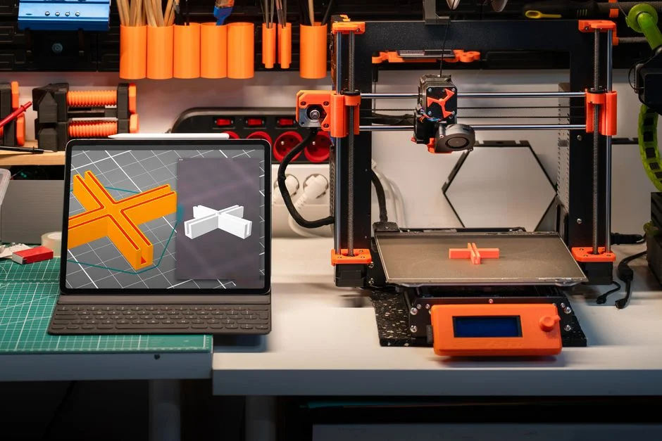
FreeCAD is frequently used as a bridge between design and physical prototypes. For 3D printing, the common path is to model a watertight solid, validate that it has no self-intersections, and export an STL mesh with appropriate resolution. Many printing issues come from design details rather than slicer settings: thin walls that don’t match nozzle width, unsupported overhangs, or tolerances that are too tight for the printer’s accuracy. A parametric approach in FreeCAD helps because you can encode clearance values and adjust them quickly. For example, a press-fit peg might need a clearance adjustment based on filament type and printer calibration. Instead of remodeling, a single parameter change can generate a revised part. That iteration speed is a major reason FreeCAD remains popular among makers building functional prints like mounts, brackets, organizers, and enclosures.
For CNC machining and subtractive processes, FreeCAD can also play a role through CAM-oriented workflows, often supported by dedicated workbenches and post-processors. Even when CAM operations are handled in separate software, FreeCAD can output STEP geometry that imports cleanly into toolpath generators. Design for manufacturing principles apply regardless of toolchain: avoid inaccessible internal corners if using end mills, provide radii compatible with cutter sizes, and consider workholding surfaces. FreeCAD’s ability to create precise geometry and generate drawings supports communication with machine shops. For laser cutting or routing, exporting 2D profiles with correct scaling and line types is important, and keeping a dedicated sketch or drawing layer for cutting profiles can reduce errors. Whether the output is additive, subtractive, or hybrid, FreeCAD’s parametric foundation helps designers dial in fits, adjust tolerances, and generate variants quickly without losing track of what changed.
Customization, Macros, and Scripting for Power Users
One of the strongest advantages of FreeCAD is its openness to customization. Users can tailor the interface, install add-ons, and automate repetitive tasks through macros and scripting. FreeCAD’s Python scripting support allows designers to generate geometry programmatically, modify parameters in bulk, and create custom tools that match a specific workflow. This matters when projects involve repeated patterns, configurable product lines, or standardized company templates. Instead of manually editing dozens of parts, a script can update key dimensions across files, regenerate models, and export outputs in a consistent way. That level of automation can be transformative for small teams that need to move fast without the overhead of expensive product lifecycle tools.
Macros also help bridge gaps between ideal workflows and real constraints. A user might create a macro to rename objects consistently, batch-export STEP and STL files, or apply standard view settings for TechDraw pages. Over time, these small automations reduce friction and improve consistency. Customization extends to preferences like navigation style, unit systems, and display settings. For teams, sharing a set of macros and configuration guidelines can create a more uniform environment, reducing onboarding time for new contributors. FreeCAD’s community has produced a large collection of scripts and add-ons, and while quality varies, many tools are mature enough for serious use. For anyone evaluating CAD platforms, the ability to inspect and extend behavior is not just a technical curiosity; it’s a practical advantage that can keep a workflow sustainable as requirements expand beyond what the default tools cover.
Performance, Stability, and Best Practices for Larger Models
As FreeCAD projects grow, performance and stability become important considerations. Large assemblies, complex fillets, and heavy use of patterns can increase recompute time. Good modeling practices can reduce the burden: keep features as simple as possible, avoid unnecessary high-resolution meshes during design, and suppress or postpone expensive operations until late in the process. For example, fillets are often computationally costly and can fail when upstream geometry changes. Applying fillets near the end, and using consistent radii that match manufacturing constraints, can make models both faster and more reliable. Similarly, patterns can be optimized by patterning sketches or features thoughtfully, rather than duplicating entire bodies when not needed. FreeCAD provides tools for managing visibility and working with subsets of a project, which can help keep the interactive experience smooth.
Stability also depends on how references are created. Many CAD failures come from referencing edges that are likely to change when a dimension updates. FreeCAD users commonly mitigate this by referencing datum planes, master sketches, and stable faces that are less likely to be replaced. Naming objects clearly helps when diagnosing issues: a tree full of “Sketch001” and “Pad003” becomes difficult to maintain, while meaningful names like “MountingHolePattern” or “LidSealGroove” make revisions safer. Another best practice is to save versions incrementally, especially before major refactors. This creates a rollback path if a change triggers unexpected recompute errors. For collaboration, using consistent FreeCAD versions and documenting add-on dependencies can prevent “works on my machine” problems. With these habits, FreeCAD can scale from small parts to substantial projects while remaining manageable and predictable over time.
Choosing FreeCAD for Learning, Hobby Work, or Professional Prototyping
FreeCAD occupies a unique space: it is approachable for learning CAD fundamentals while also being capable enough for serious prototyping and small-scale production work. For learners, the parametric approach teaches valuable concepts—constraints, references, feature history—that transfer to other CAD platforms. For hobbyists, FreeCAD offers a cost-effective way to design functional parts for 3D printing, woodworking jigs, electronics projects, and home repairs. For professionals and startups, FreeCAD can be a practical tool for early-stage design and iteration, especially when budgets are tight or when open formats and scriptability are priorities. The key is aligning expectations with workflow needs. If a project requires advanced simulation, specialized industry toolsets, or tightly integrated enterprise data management, additional tools may be necessary. But for a large range of mechanical design tasks, FreeCAD provides a credible foundation.
Adoption success often comes down to building repeatable habits: start with clean sketches, encode design intent with constraints and expressions, structure the model tree logically, and export using formats that match downstream requirements. Many users find that once they invest time in learning sketch constraints and feature ordering, their productivity increases significantly. The community ecosystem also adds long-term value: tutorials, forums, and add-ons reduce barriers and provide multiple ways to solve problems. Whether the goal is to create a single custom bracket or to develop a configurable product line, FreeCAD can support a methodical, parametric workflow that stays adaptable as requirements change. In that sense, FreeCAD is not only a tool for making shapes; it is a tool for building maintainable designs that can evolve without starting over.
Practical Tips for Getting Consistent Results and Avoiding Common Pitfalls
Consistency in FreeCAD comes from a few practical decisions made early and applied repeatedly. First, choose a unit system and stick to it across files, exports, and drawings. Second, anchor sketches to stable references such as the origin, principal planes, or datum geometry, rather than attaching sketches to faces that may change. Third, use symmetry whenever it reflects real design intent, because symmetry constraints reduce sketch complexity and make later edits more predictable. Fourth, name important dimensions and use expressions to tie related values together. This turns a model into a controlled system where changes are deliberate. Many FreeCAD users also benefit from a “master parameter” approach, where a spreadsheet or a set of named parameters drives key dimensions like thickness, clearances, and hole sizes. That reduces the chance of inconsistent edits and makes it easier to generate variants.
Another frequent pitfall is over-detailing too early. Threads, tiny chamfers, decorative fillets, and cosmetic features can slow recompute and increase failure risk. A practical approach is to model functional geometry first, verify fit, then add finishing features once the part is stable. When importing external geometry, treat it as reference and avoid building fragile dependencies on edges that may not remain consistent. For exports, verify that the chosen format matches the target: STEP for precise solids, STL for printing meshes, and DXF for 2D cutting profiles. Before sending files to manufacturing, run a sanity check: confirm dimensions, check that the solid is valid, and ensure that drawings reflect the latest model state. These habits are not unique to any one CAD system, but they are especially valuable in FreeCAD because they align with how the parametric engine and workbenches operate. With a disciplined approach, FreeCAD becomes a reliable daily driver rather than a tool that requires constant troubleshooting.
Final Thoughts on Using FreeCAD Effectively
FreeCAD rewards users who treat modeling as a structured process: define intent in sketches, build features in a stable order, and keep references resilient so that changes don’t cascade into failures. Its workbench-based design, open ecosystem, and parametric core make it suitable for a wide range of tasks, from quick prototypes to carefully documented parts. The learning curve is real, but it is also meaningful: the skills developed through constraints, expressions, and feature planning translate into better design thinking and more maintainable models. When paired with sensible export practices and clear documentation, FreeCAD can function as a central tool in a modern maker or small engineering workflow.
For anyone seeking a flexible, scriptable, and community-driven CAD solution, FreeCAD stands out as an option that can grow with the complexity of projects over time. The most successful users tend to build a repeatable workflow, avoid fragile references, and leverage parameters to handle variation without rework. Whether the goal is a single printable part, a set of CNC-ready components, or a documented design package, FreeCAD can deliver dependable results when used with intention and care.
Watch the demonstration video
In this video, you’ll learn how to get started with FreeCAD and build accurate 3D models using its parametric workflow. It covers the essential tools and workbenches, basic sketching and constraints, and how to turn sketches into solid parts. You’ll also pick up practical tips for organizing your project and refining designs efficiently.
Summary
In summary, “freecad” is a crucial topic that deserves thoughtful consideration. We hope this article has provided you with a comprehensive understanding to help you make better decisions.
Frequently Asked Questions
What is FreeCAD used for?
FreeCAD is an open-source parametric 3D CAD tool used for mechanical design, product modeling, architecture, and generating technical drawings.
Is FreeCAD really free and open source?
Yes. FreeCAD is free to use, and its source code is publicly available under an open-source license.
What does “parametric” mean in FreeCAD?
Parametric modeling is all about building a design around constraints and adjustable parameters, so when you tweak a dimension later, the entire model updates automatically—making iterative changes in **freecad** fast, flexible, and reliable.
Which file formats can FreeCAD import and export?
FreeCAD commonly supports STEP, IGES, STL, OBJ, DXF, and SVG, with availability depending on installed add-ons and settings.
How do I create a 2D drawing from a 3D model in FreeCAD?
Use the TechDraw workbench in **freecad** to turn your 3D part or assembly into clean, detailed drawing views, then export the finished sheet as a PDF or SVG.
Why do sketches fail to constrain in FreeCAD?
Issues like this are often caused by missing or conflicting constraints, accidentally creating duplicate geometry, or referencing the wrong edges or points. In **freecad**, the Sketcher solver messages are your best guide—check them to pinpoint exactly what’s under- or over-constrained and fix it quickly.
📢 Looking for more info about freecad? Follow Our Site for updates and tips!

Trusted External Sources
- FreeCAD: Your own 3D parametric modeler
FreeCAD is an open-source parametric 3D modeler made primarily to design real-life objects of any size.
- Everything and anything related to FreeCAD – Reddit
r/FreeCAD: FreeCAD on Reddit: a community dedicated to the open-source, extensible & scriptable parametric 3D CAD/CAM/FEM modeler.
- Your own 3D parametric modeler – FreeCAD
FreeCAD’s development happens daily! The FreeCAD community generates weekly builds that are based on bleeding edge FreeCAD code.
- Official source code of FreeCAD, a free and opensource … – GitHub
Freedom to build what you want FreeCAD is an open-source parametric 3D modeler made primarily to design real-life objects of any size.
- (1) Invalid length constraint – FreeCAD Forum
When i try to apply a length constraint to a line in the sketch editor i get the error “datum {length} for the constraint with index {index of the constraint} … If you’re looking for freecad, this is your best choice.