Moving from stl to gcode is the core workflow that turns a digital shape into a physical object, and it explains why a model that looks perfect on screen can still fail during printing. STL is a geometry container: it describes the surface of a model using triangles, with no native awareness of walls, print speeds, temperatures, or even “inside vs. outside” in a manufacturing sense. G-code, on the other hand, is a manufacturing instruction set, usually a long list of commands that tell a machine exactly where to move, how fast to move, when to extrude plastic, how much to extrude, and when to switch fans or change temperatures. The difference matters because the conversion from a surface mesh to machine actions requires interpretation. That interpretation is done by a slicer, and the slicer’s decisions—layer height, line width, infill pattern, retractions, seam placement, acceleration limits—can change strength, surface finish, and print success more than the visual quality of the original mesh. Thinking clearly about what each file type represents prevents common frustrations, such as assuming that a “high-resolution STL” automatically produces a smooth print, or believing that a printer can “just read STL” without context.
Table of Contents
- My Personal Experience
- Understanding STL and G-code in Modern 3D Printing
- How the STL to G-code Conversion Actually Works
- Preparing a Clean STL for Reliable Slicing
- Choosing the Right Slicer and Printer Profile
- Core Slicer Settings That Shape Print Quality
- Supports, Adhesion, and Orientation Choices
- Common Conversion Problems and How to Fix Them
- Expert Insight
- Advanced Techniques: Variable Layers, Adaptive Infill, and Seam Control
- Material-Specific Considerations During Slicing
- Checking the G-code Preview Like a Technician
- Workflow Tips for Faster, More Consistent Results
- Final Thoughts on Converting STL to Printer-Ready Toolpaths
- Frequently Asked Questions
My Personal Experience
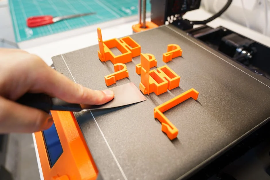
The first time I tried going from an STL to G-code, I assumed it was basically a “save as” step and couldn’t figure out why my printer kept making a stringy mess. I’d downloaded a simple bracket STL, dropped it into Cura, hit slice, and sent the file over—only to realize later I’d left the default profile on the wrong nozzle size and my layer height was way too aggressive for the cheap PLA I was using. After a couple failed prints, I started paying attention to the preview, checking the walls and supports, and tweaking temperature and retraction before exporting the G-code. Once I slowed the print down and fixed the bed leveling, the same STL finally came out clean, and it clicked for me that the slicer settings matter just as much as the model. If you’re looking for stl to gcode, this is your best choice.
Understanding STL and G-code in Modern 3D Printing
Moving from stl to gcode is the core workflow that turns a digital shape into a physical object, and it explains why a model that looks perfect on screen can still fail during printing. STL is a geometry container: it describes the surface of a model using triangles, with no native awareness of walls, print speeds, temperatures, or even “inside vs. outside” in a manufacturing sense. G-code, on the other hand, is a manufacturing instruction set, usually a long list of commands that tell a machine exactly where to move, how fast to move, when to extrude plastic, how much to extrude, and when to switch fans or change temperatures. The difference matters because the conversion from a surface mesh to machine actions requires interpretation. That interpretation is done by a slicer, and the slicer’s decisions—layer height, line width, infill pattern, retractions, seam placement, acceleration limits—can change strength, surface finish, and print success more than the visual quality of the original mesh. Thinking clearly about what each file type represents prevents common frustrations, such as assuming that a “high-resolution STL” automatically produces a smooth print, or believing that a printer can “just read STL” without context.
STL files also have limitations that influence the conversion pipeline. Since STL stores only triangles, it can’t preserve parametric features like “this is a hole of diameter 8 mm” or “this wall must be 1.6 mm thick.” The slicer infers thickness and features by slicing the mesh at successive heights, turning the cross-sections into toolpaths. If the mesh has errors—non-manifold edges, self-intersections, flipped normals, tiny gaps—the slicer may produce broken perimeters or missing layers, which then become flawed G-code. G-code is similarly constrained: it is often tailored to a specific firmware dialect (Marlin, Klipper, RepRapFirmware, etc.), and different printers interpret the same command differently depending on settings like steps-per-mm, extrusion mode (absolute vs. relative), and motion limits. Successful conversion from STL to printer instructions therefore requires not only a clean model but also a slicer profile that matches the machine, filament, and intended use. When these pieces align, the resulting toolpath is predictable, repeatable, and easy to troubleshoot. If you’re looking for stl to gcode, this is your best choice.
How the STL to G-code Conversion Actually Works
The jump from mesh geometry to toolpath is not a single “save as” operation; it’s a series of computational steps that a slicer performs to translate triangles into printable layers. During stl to gcode conversion, the slicer first loads the mesh and checks it for basic integrity: it determines the model’s bounding box, identifies connected components, and attempts to interpret the surface as a closed volume. Next, it intersects the model with a stack of horizontal planes at the chosen layer height (and sometimes variable layer heights). Each intersection produces one or more 2D polygons that represent the outer boundary of the part at that Z height. Those polygons are then offset inward to generate perimeters (shells) based on the selected line width and number of walls. After the walls are planned, the slicer fills the remaining internal area with infill, which is generated as a pattern of lines or curves with controlled spacing, angle changes, and density. Top and bottom surfaces are treated specially, with solid layers and skin patterns to close the part. Finally, supports, brims, rafts, and other adhesion structures are computed as separate toolpaths that must be printed in a specific order to avoid collisions and maximize stability.
Once the toolpath geometry exists, the slicer assigns process parameters to each segment: speed, acceleration hints, extrusion amount, fan settings, and temperatures. Extrusion is calculated from the path length, layer height, and line width, adjusted by flow multipliers and filament diameter. The slicer also injects retraction moves, wipe sequences, coasting, pressure advance hints (depending on firmware), and travel moves that avoid crossing perimeters where possible. The outcome is emitted as G-code, typically a text file starting with startup commands (homing, heating) and ending with shutdown commands (cooling, motors off). Each line might look like “G1 X120.4 Y85.2 E0.412 F1800,” which means move in a straight line to a coordinate while extruding a certain amount at a feed rate. This is where printer specificity matters: the same G-code can behave differently if the printer uses different kinematics (Cartesian vs. CoreXY vs. Delta), different nozzle size, or different extrusion calibration. Understanding these stages makes it easier to diagnose issues: if a hole is undersized, it’s often a perimeter offset and shrinkage issue; if layers separate, it’s often temperature, speed, or cooling; if the first layer is rough, it’s bed leveling and Z offset; if supports are fused, it’s support interface and Z gap. The slicer is the translator, and its translation choices define the physical result. If you’re looking for stl to gcode, this is your best choice.
Preparing a Clean STL for Reliable Slicing
Before any slicer can do a dependable stl to gcode conversion, the STL must represent a watertight, well-defined solid. A “watertight” mesh means the surface is closed with no holes, and every edge belongs to exactly two triangles, forming a manifold. Non-manifold geometry is one of the most common causes of strange slicing behavior: missing top layers, internal voids that shouldn’t exist, or perimeters that abruptly stop. Another frequent issue is inverted normals, where some triangles face inward while others face outward; slicers may treat inward faces as “outside,” leading to incorrect volume interpretation. Self-intersections—where parts of the mesh pass through each other—can also confuse the creation of cross-sectional polygons, especially around thin features. Even if the model looks fine visually, these mesh pathologies can cause the slicer to generate toolpaths that don’t match intent. Repairing the STL using mesh tools (Netfabb-like repair, Meshmixer analysis, Blender cleanup, CAD re-export with better tessellation) can dramatically improve success rate. The goal is to provide the slicer with a clear, unambiguous solid so it can generate perimeters and infill consistently.
Mesh resolution is another area where preparation matters, but it is often misunderstood. A very low-resolution STL can produce faceted curves, which may become visible on the print, especially on cylindrical surfaces. However, an extremely high-resolution STL with millions of triangles can slow slicing, inflate file size, and sometimes introduce tiny triangle noise that creates micro-jitter in the toolpath. The best approach is “appropriate tessellation”: enough triangles to represent curvature smoothly at the scale your printer can reproduce, but not so many that the slicer becomes inefficient. If your nozzle is 0.4 mm and your layer height is 0.2 mm, details smaller than that are unlikely to print meaningfully, so the mesh doesn’t need sub-micron triangle density. Also consider unit consistency: STL files don’t store units explicitly, so a model designed in inches may import as millimeters at the wrong scale. Verifying dimensions in the slicer—checking known lengths, hole diameters, and thicknesses—prevents scaling mistakes that waste time and material. Finally, look at minimum feature thickness: if walls are thinner than the nozzle line width or not a multiple of it, the slicer may either ignore them or produce a single fragile line. Adjusting the model or choosing “thin wall” features in the slicer can help, but the most reliable path is designing with the printer’s extrusion width in mind. Clean geometry plus realistic feature sizing makes the conversion to printer instructions predictable and repeatable. If you’re looking for stl to gcode, this is your best choice.
Choosing the Right Slicer and Printer Profile
The slicer is the engine of stl to gcode conversion, and different slicers prioritize different strengths: speed, advanced features, surface quality, multi-material control, or ease of setup. Cura, PrusaSlicer, OrcaSlicer, Bambu Studio, Simplify3D, and others all generate G-code, but their defaults and algorithms vary. For example, one slicer might produce more conservative accelerations, while another emphasizes faster travel with more aggressive retraction. Some slicers offer sophisticated seam hiding, scarf joints, or adaptive pressure control integration, while others focus on stable baseline profiles. The key is not brand loyalty but matching the slicer’s capabilities to your printer and goals. If you frequently print functional parts, you may value per-object settings, modifier meshes, and strong support controls. If you print aesthetic models, you may prioritize variable layer height, precise seam placement, and surface ironing. If you run Klipper, you may want slicer output that plays well with input shaping, pressure advance, and high-speed motion. Regardless of slicer, the profile is what binds the toolpath to the machine’s physical reality: build volume, origin placement, start/end sequences, retraction distances, nozzle diameter, and temperature ranges.
A printer profile should be treated like a calibrated manufacturing recipe, not a generic template. Start by confirming nozzle size, filament diameter (usually 1.75 mm or 2.85 mm), and firmware flavor, then verify extrusion mode (absolute E vs. relative E). Make sure the bed size, coordinate system, and homing directions are correct, especially if your printer has a nonstandard origin or uses a probe with offsets. Temperature settings should match the material and the hotend’s capability; some hotends struggle with high flow at lower temperatures, which can cause under-extrusion that looks like “bad slicing” but is actually a melt limitation. Cooling should be tuned for bridging and overhangs: too much fan can weaken layer adhesion in materials like ABS, while too little fan can ruin PLA overhangs. Retraction and travel settings also matter: direct-drive extruders typically need shorter retractions than Bowden setups, and too much retraction can cause jams or stringing oscillations. Many profiles include acceleration and jerk (or junction deviation) hints; if these exceed what your machine can handle mechanically, you get ringing, skipped steps, or dimensional inaccuracies. A strong profile makes the G-code “machine-friendly,” meaning it respects motion limits, keeps extrusion stable, and avoids unnecessary travel moves. When the profile is correct, the same STL consistently produces predictable results, and adjustments become systematic rather than guesswork. If you’re looking for stl to gcode, this is your best choice.
Core Slicer Settings That Shape Print Quality
The most influential settings in stl to gcode conversion are layer height, line width, wall count, top/bottom thickness, and infill strategy. Layer height controls vertical resolution and strength trade-offs: smaller layers can improve surface smoothness on sloped surfaces and increase detail, but they also increase print time and may reduce inter-layer bonding if temperatures and speeds are not tuned. Line width (often near nozzle diameter, sometimes slightly larger) determines how the slicer packs material into features; thicker lines can improve strength and reduce print time, but can blur fine details and reduce dimensional precision on small holes or thin walls. Wall count and thickness matter for both strength and appearance: more perimeters increase stiffness and improve impact resistance, while too few walls can make parts brittle even if infill is high. Top and bottom thickness ensures surfaces close properly; insufficient top layers can cause “pillowing,” where infill shows through, while insufficient bottom layers can cause weak bases or poor aesthetics. These settings interact: a 0.2 mm layer height with a 0.45 mm line width behaves differently than a 0.12 mm layer height with a 0.42 mm line width, even on the same nozzle, because extrusion volume and cooling dynamics change.
Infill is often overemphasized compared to walls, but it still matters in specific ways. The infill pattern affects how loads transfer through the part: gyroid is isotropic and good for strength, grid can be stiff but may print with more vibration, and cubic or adaptive infill can save time and material while supporting top layers. Infill density should be chosen based on function; many functional prints benefit more from extra walls than from pushing infill from 20% to 60%. Another important setting is the order of printing features: printing inner walls before outer walls can improve dimensional accuracy in some cases, while outer-first can improve surface finish depending on material and cooling. Seam position and alignment affect visible artifacts; random seams can hide a vertical line but may create small zits across the model, while aligned seams produce one more noticeable line. Bridging settings determine how the slicer spans gaps: bridge speed, bridge flow, and fan behavior can make the difference between clean bridges and sagging strands. Overhang settings, including minimum layer time and cooling thresholds, influence whether small features deform from heat buildup. When you understand how these parameters affect the generated toolpaths, you can adjust them intentionally rather than chasing symptoms. The conversion is not merely about producing any G-code; it’s about producing G-code that matches the desired mechanical properties, finish, and reliability for the specific model. If you’re looking for stl to gcode, this is your best choice.
Supports, Adhesion, and Orientation Choices
Print orientation is one of the most powerful “invisible” decisions in stl to gcode conversion because it determines where supports are needed, how strong the part is along different axes, and what surfaces end up visible. FDM parts are anisotropic: they are typically strongest along the filament lines and weaker between layers. Orienting a functional hook so that the load pulls along continuous perimeters can dramatically increase strength compared to an orientation that loads the layer interfaces. Orientation also affects surface finish: the top surfaces can be smooth, while downward-facing surfaces may show support marks or droop. Rotating the part to place critical surfaces upward, reduce steep overhangs, or minimize support contact can save time and improve aesthetics. Even small rotations can change how seams align and how travel paths cross visible areas. A practical approach is to preview the sliced layers and identify where the slicer will start/stop perimeters, where it will bridge, and where it will need supports, then choose an orientation that makes those compromises acceptable.
Support generation is a balance between printability and post-processing. Tree supports can reduce scarring and material use on organic models, while grid supports can be more stable for large flat overhangs. Support interface layers (dense “roof” layers) can improve the underside finish but may increase removal difficulty if the Z-gap is too small. The support Z-distance and XY separation determine how easily supports detach and how clean the underside looks; too tight and supports fuse, too loose and overhangs sag. Adhesion strategies—skirt, brim, raft—also influence success. A brim increases first-layer footprint and reduces warping on sharp corners, especially for materials that shrink. A raft can help on uneven beds or difficult materials, but it adds time and can degrade bottom-surface quality. First-layer settings are often more important than people expect: a slightly higher first-layer temperature, slower speed, and slightly thicker first layer can improve bonding and compensate for minor leveling errors. In the slicer preview, it’s worth inspecting the first layer path density and checking whether small islands are present; tiny isolated features may detach unless you add a brim, increase first-layer flow, or redesign the model. These decisions are all encoded into the final machine instructions, so thoughtful support and adhesion choices often matter more than swapping filaments or chasing exotic settings. If you’re looking for stl to gcode, this is your best choice.
Common Conversion Problems and How to Fix Them
When stl to gcode conversion goes wrong, the symptoms often show up in the preview before a single gram of filament is used. Missing layers, holes in the model, or strange internal gaps can indicate a non-watertight mesh or overlapping shells. If the slicer shows “thin air” where plastic should be, try enabling mesh repair features, re-exporting from CAD with a proper solid, or running a mesh fix that closes holes and resolves non-manifold edges. Another typical issue is extremely thin features: the slicer may ignore walls that are below a certain threshold or may print them as a single line that doesn’t bond well. Adjusting line width, enabling “print thin walls,” or redesigning to multiples of extrusion width can solve it. If the preview shows zig-zagging travel moves through perimeters, you may need to tune combing or avoid-crossing-perimeters settings, or adjust retraction to reduce stringing. If the preview shows excessive retractions and short segments, it might be a sign of overly fine mesh triangles creating noisy toolpaths; simplifying the mesh or enabling arc fitting (where supported) can smooth motion.
| Option | Best for | Pros | Cons |
|---|---|---|---|
| Slicer software (e.g., Cura, PrusaSlicer) | Most FDM 3D printing workflows converting STL to G-code | Fast setup, print profiles, supports supports/infill, wide printer compatibility | Requires tuning for best quality; settings can be overwhelming for beginners |
| CAM toolpaths (CNC-style) for 3D reliefs | Generating G-code for machining or specialized toolpath needs | Precise control over toolpaths, feeds/speeds, and machining strategies | Not ideal for typical FDM printing; steeper learning curve |
| Online STL-to-G-code converters | Quick tests, simple models, or when you can’t install software | No install, convenient, often includes basic slicing presets | Limited control, privacy/file-size limits, results may be inconsistent across printers |
Expert Insight
Before converting an STL to G-code, repair the mesh and confirm the model’s scale and orientation. Use a mesh fixer to close holes and remove non-manifold edges, then place the flattest face on the build plate to reduce supports and improve first-layer adhesion. If you’re looking for stl to gcode, this is your best choice.
In the slicer, calibrate for your material and nozzle by running a quick temperature tower and a flow/extrusion test, then lock in settings. Start with a conservative layer height (e.g., 0.2 mm for a 0.4 mm nozzle), set 3–4 perimeters for strength, and preview the toolpaths to catch thin walls, missing features, or excessive retractions before exporting G-code. If you’re looking for stl to gcode, this is your best choice.
Dimensional inaccuracies are another frequent complaint, and they can be caused by both slicing and machine calibration. Holes often print undersized due to plastic shrinkage and how perimeters are approximated; compensations like horizontal expansion, hole compensation, or simply designing holes slightly larger can help. Elephant’s foot—bulging at the bottom—often comes from a too-squished first layer or bed temperature effects; slicer features like elephant foot compensation, reducing first-layer flow, or adjusting Z offset can correct it. If walls appear wavy or corners are rounded, it may be acceleration limits and ringing; reducing speed, tuning input shaping, or tightening belts can help, but you can also reduce abrupt direction changes by selecting different infill patterns. Under-extrusion can look like gaps in top layers or weak perimeters; confirm filament diameter, flow rate, nozzle cleanliness, and that the chosen print temperature matches the volumetric flow demanded by the G-code. Over-extrusion can cause blobs and poor surface finish; tune extrusion multiplier and ensure correct E-steps (or rotation distance) calibration. Many “conversion” issues are actually mismatches between what the slicer assumes and what the printer can physically deliver. The fastest path to stability is to validate the preview, verify profile correctness, and adjust one variable at a time while observing how toolpath changes influence the print outcome. If you’re looking for stl to gcode, this is your best choice.
Advanced Techniques: Variable Layers, Adaptive Infill, and Seam Control
Once the basics are reliable, advanced slicer features can significantly improve results from stl to gcode conversion without changing the underlying model. Variable layer height is a prime example: the slicer uses smaller layers on steep slopes and detailed areas, and larger layers on vertical walls. This can reduce print time compared to uniformly small layers while keeping surface quality where it matters. The key is to review the layer height map and ensure transitions are smooth; abrupt changes can sometimes show as bands. Adaptive infill or infill modifiers can also optimize prints by increasing density only where needed—around screw bosses, load-bearing areas, or under top surfaces—while leaving other regions lighter. Some slicers allow “support blockers” and “support enforcers” to fine-tune where supports appear, which is especially helpful for models with internal cavities or delicate details. Another powerful tool is per-object settings: printing different parts of a build plate with different temperatures, walls, or infill, useful for prototypes where you want to compare strength variants in one run.
Seam control is often the difference between a print that looks professional and one that looks hobby-grade. By setting seam position to a sharp corner, a rear face, or a least-visible region, you can hide the start/stop artifacts. Some slicers offer seam painting, allowing you to “draw” where seams should go. Coasting, wipe, and retraction tuning can reduce zits, but these must match the extrusion system; too aggressive coasting can create gaps, and too aggressive wiping can thin walls. Another advanced consideration is arc fitting (G2/G3) versus many small line segments (G1). Some slicers can output arcs for smoother motion and smaller files, but firmware support varies. For high-speed printing, integrating pressure advance (or linear advance) and respecting volumetric flow limits becomes critical; slicers may offer maximum volumetric speed settings to prevent commanding more plastic than the hotend can melt. These techniques are not about adding complexity for its own sake; they are about encoding smarter manufacturing intent into the toolpath so the printer spends time and material where it produces visible or structural improvements. If you’re looking for stl to gcode, this is your best choice.
Material-Specific Considerations During Slicing
Different filaments respond differently to the same stl to gcode settings because they have distinct melting behavior, shrinkage rates, and cooling needs. PLA tends to print easily with strong cooling and moderate temperatures, producing sharp details and good bridging, but it can become brittle under heat or impact. PETG often needs less fan to avoid poor layer bonding and stringing; it also benefits from slightly higher temperatures and careful retraction tuning to prevent blobs. ABS and ASA shrink more, making warping and layer splitting common; they often require enclosure heat, reduced fan, higher bed temperatures, and sometimes brims to keep corners down. TPU and other flexible filaments print slowly, with minimal retraction and gentle accelerations, and they can be sensitive to sharp path changes that cause filament buckling. Nylon can absorb moisture quickly and may need drying; it can also warp and requires careful bed adhesion. Each material’s behavior should influence how you configure perimeters, speeds, and cooling, because those choices become hard-coded into the G-code.
Material also affects design interpretation. For example, thin walls in PLA may be fine for decorative parts, but the same geometry in PETG might flex and show stringing at seams unless seam placement is optimized. For ABS/ASA, increasing wall count and using rounded corners can reduce stress concentration and warping. For PETG, slightly increasing Z-hop can prevent nozzle drag on tall prints, but too much Z-hop can increase stringing; it’s a balance. For high-flow materials or larger nozzles, consider increasing line width and layer height to keep extrusion consistent and reduce print time, but be mindful that overhang performance may worsen without sufficient cooling. Moisture sensitivity is often misdiagnosed as “bad slicing” because it shows as popping, rough surfaces, and inconsistent extrusion; if the filament is wet, no amount of toolpath perfection will fully compensate. A practical method is to maintain separate slicer profiles per material and nozzle size, with temperature towers and retraction tests used to validate each profile. That way, the conversion from STL to machine instructions is not generic; it is tuned to the polymer’s real-world behavior and the printer’s thermal and motion capabilities. If you’re looking for stl to gcode, this is your best choice.
Checking the G-code Preview Like a Technician
Before sending a file to the printer, the preview is your best window into whether stl to gcode conversion produced sensible manufacturing instructions. Start by scanning the first few layers: confirm the skirt or brim is present if needed, verify perimeters are continuous, and ensure small features have adequate contact with the bed. Look for isolated “dots” or tiny islands that could detach; if they exist, consider adding a brim, changing orientation, or merging features. Next, move through the layers at points where geometry changes—overhang starts, bridges begin, internal cavities close, or supports engage. Pay attention to the order of operations: if the slicer prints small towers too quickly, heat can accumulate and cause deformation; minimum layer time settings may slow those layers or raise the nozzle for cooling moves. Also inspect travel moves: frequent long travels across open areas can increase stringing risk, while travel paths that cross outer walls can leave scars. Many slicers color-code speed, flow, or feature type, which helps you spot if bridges are being printed too fast or if the outer wall speed is too high for the desired finish.
It’s also worth reviewing estimated volumetric flow and time per feature. If the slicer commands extremely high flow on thick layers and wide lines, the hotend may not keep up, causing under-extrusion. If the preview shows very dense support under a delicate surface, support removal may be difficult; adjust interface layers, density, or Z-gap. Check seam placement in the preview if your slicer marks it; if seams land on the most visible face, rotate the model or change seam settings. For multi-part plates, confirm that the print order doesn’t risk collisions; sequential printing can be efficient but requires clearance. Finally, review the start and end G-code: ensure it homes correctly, heats in the right order, primes the nozzle, and avoids crashing into clips or bed edges. A careful preview review can catch 80% of print failures before they happen, and it turns slicing from a passive step into an active quality control process. The more you learn to “read” the toolpath, the more predictable your prints become, even with complex geometries. If you’re looking for stl to gcode, this is your best choice.
Workflow Tips for Faster, More Consistent Results
Efficiency in stl to gcode conversion comes from standardizing decisions and reducing variables. Keeping a small library of validated profiles—organized by printer, nozzle size, and material—prevents accidental mixing of settings that lead to inconsistent results. Name profiles clearly (for example, “0.4mm PLA Quality 0.16” or “0.6mm PETG Draft 0.32”) and record the filament brand and typical temperatures that work. When you change a major component, like a hotend, extruder, or firmware, treat it as a new baseline and re-validate flow, retraction, and temperature. For models you print repeatedly, save project files that preserve orientation, support blockers, seam painting, and per-part modifiers; relying on memory invites subtle mistakes. Another helpful practice is to keep a set of calibration models—temperature tower, retraction test, bridge test, overhang test—and rerun them when you switch to a new filament spool or after mechanical changes. These prints are small investments that pay back by making the generated G-code better aligned with reality.
Consistency also improves when design and slicing are aligned. If you design parts yourself, model wall thicknesses and clearances around your printer’s typical extrusion width and tolerances, rather than expecting the slicer to “figure it out.” For assemblies, incorporate clearance values that match your material shrink and your machine’s dimensional behavior; PETG often needs different clearances than PLA, and ABS may need even more. If you download models, don’t hesitate to modify them—adding chamfers to reduce elephant’s foot, thickening thin walls, or splitting a model to avoid excessive supports. Automate repetitive steps where possible: many slicers support command-line slicing or batch processing, which is useful for iterating settings systematically. Finally, keep your G-code organized and traceable: include slicer metadata in filenames (material, nozzle, layer height) and store the corresponding STL version. That way, when a print succeeds, you can reproduce it reliably, and when it fails, you can identify what changed. A disciplined workflow turns STL conversion from an art into a controlled process where improvements are measurable and repeatable. If you’re looking for stl to gcode, this is your best choice.
Final Thoughts on Converting STL to Printer-Ready Toolpaths
Reliable stl to gcode conversion is less about finding a single “best” slicer setting and more about building a chain of correctness: a clean, well-scaled mesh; a printer profile that matches firmware and hardware; material-appropriate temperatures and cooling; and a preview-driven quality check before printing. When those pieces are in place, the slicer’s output becomes predictable, and troubleshooting becomes straightforward because each symptom points to a narrow set of causes. Strong results come from respecting what STL is (surface geometry) and what G-code is (machine motion and extrusion commands), then making intentional choices at the translation stage so the machine instructions reflect the part’s functional and aesthetic goals.
The most practical mindset is to treat slicing as manufacturing planning rather than a clerical export step. Orientation, supports, wall strategy, seam placement, and speed limits are all decisions that define the final object as much as the original model does. By repairing meshes when needed, calibrating profiles, and reading the preview like a technician, you can consistently produce G-code that prints cleanly on your specific machine. Over time, the process becomes faster because you recognize patterns: which geometries need brims, which materials need lower fan, which holes need compensation, and which seams should be hidden. With that experience, stl to gcode stops being a source of surprises and becomes a repeatable pipeline that turns ideas into durable, accurate prints.
Summary
In summary, “stl to gcode” is a crucial topic that deserves thoughtful consideration. We hope this article has provided you with a comprehensive understanding to help you make better decisions.
Frequently Asked Questions
What’s the difference between STL and G-code?
An STL file captures the shape and geometry of a 3D model, but a printer or CNC machine can’t use it directly—those devices rely on G-code, which contains the step-by-step commands for building or cutting the part. That’s why converting **stl to gcode** is a crucial step in turning a design into a finished physical object.
Can I convert an STL directly to G-code?
Not directly with a simple converter—STL must be processed by slicer/CAM software that generates G-code based on print/machine settings.
What software can convert STL to G-code for 3D printing?
Common slicers include Cura, PrusaSlicer, Bambu Studio, and Simplify3D; they import STL and export printer-ready G-code.
Why does my G-code look wrong even though the STL is fine?
Even with a perfectly designed model, the final print can still fail if your slicer settings are off—things like the printer profile, nozzle size, temperatures, layer height, support setup, or scaling all shape the toolpath created during **stl to gcode** conversion, and small mistakes there can lead to poor results.
How do I choose the right settings when generating G-code from STL?
Begin by selecting the right printer profile, then dial in your material temperatures, layer height, infill, supports, and print speeds. Once everything looks good, preview the toolpath to catch any issues, and then export your file—converting **stl to gcode** for a smooth, reliable print.
Is STL-to-G-code the same process for CNC machining?
Not really—most CNC workflows rely on CAM software to generate accurate toolpaths and usually work best with CAD formats like STEP or IGES. While converting **stl to gcode** is possible in certain cases, STL meshes often lack the precision and clean geometry needed for high-quality machining, which can lead to rougher results and extra cleanup.
📢 Looking for more info about stl to gcode? Follow Our Site for updates and tips!