tinkercad 3d printing has become a common entry point for people who want to move from an idea to a physical object without wrestling with complicated professional CAD packages. Tinkercad is a browser-based modeling environment that emphasizes simple shapes, intuitive controls, and rapid iteration, which aligns perfectly with the mindset needed for additive manufacturing. When a design tool makes it easy to sketch, adjust, and test proportions quickly, users spend more time refining the object for real-world use and less time learning software mechanics. This matters because 3D printing is rarely a one-and-done process; most useful parts require small adjustments after the first print. A friendly design workflow makes those iterations painless. The platform also makes it straightforward to export common file formats used in fabrication, so the step from a digital model to a printable file feels natural rather than intimidating.
Table of Contents
- My Personal Experience
- Getting Started with tinkercad 3d printing: What It Is and Why It Works
- Planning a Printable Design Before You Model
- Core Tinkercad Tools That Matter Most for 3D Printing
- Designing for FDM Printers: Wall Thickness, Overhangs, and Supports
- Designing for Resin Printing: Detail, Drainage, and Post-Processing
- Measuring, Scaling, and Working with Real-World Dimensions
- Exporting Files from Tinkercad and Preparing Them for Slicing
- Expert Insight
- Common Design Mistakes and How to Fix Them in Tinkercad
- Making Functional Parts: Enclosures, Brackets, and Mechanical Fit
- Improving Print Quality with Orientation, Layer Strategy, and Iteration
- Classroom, Hobby, and Prototyping Workflows That Scale
- Final Checks Before Printing and Long-Term Success Tips
- Watch the demonstration video
- Frequently Asked Questions
- Trusted External Sources
My Personal Experience
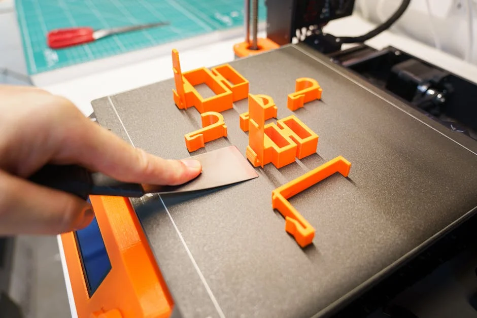
The first time I used Tinkercad for 3D printing, I kept it simple and designed a small cable clip for my desk. I liked how fast I could drag shapes around and measure everything without getting lost in complicated menus, but I still managed to mess up the scale and printed a clip that was basically dollhouse-sized. After that, I started double-checking units, using the ruler tool, and exporting the STL to my slicer with a quick preview to catch obvious mistakes. It was honestly satisfying to go from a rough idea to something I could actually snap onto a cable in an afternoon, and it made me more confident about trying slightly more detailed prints. If you’re looking for tinkercad 3d printing, this is your best choice.
Getting Started with tinkercad 3d printing: What It Is and Why It Works
tinkercad 3d printing has become a common entry point for people who want to move from an idea to a physical object without wrestling with complicated professional CAD packages. Tinkercad is a browser-based modeling environment that emphasizes simple shapes, intuitive controls, and rapid iteration, which aligns perfectly with the mindset needed for additive manufacturing. When a design tool makes it easy to sketch, adjust, and test proportions quickly, users spend more time refining the object for real-world use and less time learning software mechanics. This matters because 3D printing is rarely a one-and-done process; most useful parts require small adjustments after the first print. A friendly design workflow makes those iterations painless. The platform also makes it straightforward to export common file formats used in fabrication, so the step from a digital model to a printable file feels natural rather than intimidating.
Another reason tinkercad 3d printing is so effective is that the software encourages thinking in solids, clearances, and assemblies even at a beginner level. By combining primitives like boxes, cylinders, wedges, and holes, you can build functional geometry that translates well to fused deposition modeling (FDM) or resin printing. The “hole” tool, alignment helpers, and grouping features promote a habit of designing with subtraction and fit in mind, which is essential when parts must slide, snap, or screw together. Because the app runs in the browser, it also supports quick access from different computers, making it convenient for classrooms, makerspaces, or hobbyists who switch between devices. When paired with a basic understanding of printer limitations—like minimum wall thickness and overhang angles—Tinkercad becomes not just a learning toy but a practical design tool for everyday prints.
Planning a Printable Design Before You Model
Good tinkercad 3d printing results start before any shapes are dragged onto the workplane. Planning means deciding what the object must do, how it will be used, and what printing method will produce the most reliable outcome. If the part needs strength, consider how layer orientation will affect it; if the part needs precision, think about how your printer handles small holes and thin walls. It helps to write down the critical dimensions first, especially any interfaces with real-world items: a phone’s thickness, a screw diameter, a pipe’s outer diameter, or the spacing between mounting holes. These “must-fit” dimensions should drive the design, while the rest of the geometry can be adjusted for aesthetics or print efficiency. Even simple projects benefit from this discipline because it reduces wasted filament and time spent reprinting.
Planning also includes choosing tolerances appropriate for your machine and material. FDM printers tend to print holes slightly undersized and outer dimensions slightly oversized depending on calibration, while resin printers can capture finer detail but may shrink during curing. For tinkercad 3d printing, it’s smart to design test coupons: small samples that include the kinds of features your final part will have, such as a press-fit peg, a sliding dovetail, or a threaded region. Printing these tests early provides real feedback about what clearance values work for your setup. For example, a sliding fit might need 0.3–0.5 mm of clearance on an FDM printer, while a snap-fit might need carefully shaped hooks and a bit more thickness to avoid breakage. Planning for supports is another critical step: if you can orient the model to avoid heavy support structures, you’ll get cleaner surfaces and faster prints. Thinking about these factors upfront makes modeling in Tinkercad faster because you already know what features you must include and what shapes you should avoid.
Core Tinkercad Tools That Matter Most for 3D Printing
When focusing on tinkercad 3d printing, a handful of tools deliver most of the practical value: align, group, hole, ruler, and workplane. Align keeps parts centered or evenly spaced, which is essential for assemblies and symmetrical designs. Grouping merges multiple solids and holes into a single printable mesh, reducing the risk of accidental gaps that can confuse slicers. The hole feature is especially important because it encourages clean Boolean subtraction: instead of trying to “carve” shapes manually, you place a hole object, size it precisely, and group it with the solid. This produces consistent voids for screw channels, cable pass-throughs, and weight reduction pockets. The ruler tool enables accurate dimensioning directly on the workspace, which is crucial for parts that must fit other objects. Workplane lets you reposition your modeling reference on angled or elevated surfaces, making it easier to add features without complex transformations.
Another set of features worth mastering for tinkercad 3d printing includes duplication, mirroring, and the ability to lock shapes. Duplication speeds up repetitive geometry such as vent slots, honeycomb-like patterns, or evenly spaced mounting bosses. Mirroring helps you keep symmetrical designs consistent; instead of eyeballing two sides, you create one side and mirror it to ensure identical geometry. Locking shapes prevents accidental nudges that create tiny misalignments—small errors that can lead to uneven walls or weak points in the final print. It’s also helpful to understand how Tinkercad handles grouping: once you group objects, you can still ungroup to edit, but complex designs can become harder to manage if everything is merged too early. A practical workflow is to group in logical stages, naming or color-coding components while you work, then performing a final grouping pass before export. This approach keeps the model editable and helps reduce accidental non-manifold edges, which can appear when overlapping shapes aren’t combined cleanly.
Designing for FDM Printers: Wall Thickness, Overhangs, and Supports
Most tinkercad 3d printing projects are produced on FDM printers because they are widely available and cost-effective. Designing for FDM means respecting the way filament is deposited in layers. Wall thickness should generally be a multiple of your nozzle width; for a 0.4 mm nozzle, common perimeters are 0.8 mm, 1.2 mm, or 1.6 mm depending on strength needs. Very thin walls can slice unpredictably or print fragile, while overly thick walls can waste material and increase print time without adding meaningful strength. Overhangs are another key constraint: surfaces that extend outward without support often sag beyond about 45 degrees, though printer cooling and speed can improve that. Bridging can work surprisingly well for short gaps, but long spans tend to droop. If your design includes long horizontal openings, consider adding arches, chamfers, or internal ribs that reduce unsupported distance.
Support strategy should influence modeling choices in tinkercad 3d printing. Supports can scar surfaces and require cleanup, which is especially noticeable on decorative objects. For functional parts, support scars can affect fit and motion. Designing with “self-supporting” angles—such as chamfers instead of sharp 90-degree ledges—reduces the need for supports and improves surface quality. Another tactic is splitting a model into multiple pieces that print flat, then assembling them with screws, pins, or glue. Tinkercad makes splitting easy by using hole shapes as cutters or by creating separate components that can be exported individually. When designing snap-fits, remember that FDM layers are weakest between layers, so orient snap hooks so the bending force runs along the filament paths when possible. Also consider adding fillets or gentle curves to reduce stress concentrations; while Tinkercad doesn’t have advanced filleting like some CAD tools, you can approximate it with rounded shapes or by combining cylinders and wedges. Thoughtful design reduces print failures and produces parts that feel engineered rather than improvised.
Designing for Resin Printing: Detail, Drainage, and Post-Processing
tinkercad 3d printing isn’t limited to filament machines; resin printing is also a strong match when you need fine detail, smooth surfaces, and small features. Resin printers can capture crisp text, tiny embossing, and thin lattice structures better than most FDM setups. However, resin introduces different design constraints. Hollow parts should include drainage holes so uncured resin can escape, and these holes should be placed where they can be cleaned and later hidden or plugged if needed. Orientation is critical: a model that looks perfect on screen can trap resin in pockets, leading to messy prints and curing issues. Thin walls can be printed reliably, but they may warp during curing if not supported properly. If the goal is a durable part, consider adding internal ribs or thicker walls in stress areas, even if the outer surface remains slim and detailed.
Post-processing is a major part of resin-based tinkercad 3d printing. Supports are often required, and removing them can leave marks. Designing support-friendly contact areas—like placing supports on hidden surfaces—improves the final appearance. Sharp edges and fragile projections may break during washing or support removal, so slightly thickening delicate parts can prevent heartbreak. Another important consideration is tolerances: resin prints can be accurate, but dimensional changes can occur due to resin type, exposure settings, and curing time. For mating parts, it helps to include adjustable clearance in the design and then refine after a test print. Tinkercad can handle this iterative approach well: duplicate the design, modify only the critical dimensions, and keep a version history. Even for artistic prints, this approach saves time because you can dial in a consistent fit for bases, lids, or modular pieces. With careful planning, resin output can look professional while still benefiting from Tinkercad’s simple modeling workflow.
Measuring, Scaling, and Working with Real-World Dimensions
Accurate sizing is at the heart of successful tinkercad 3d printing. A model that looks right visually can still fail if a slot is 0.5 mm too narrow or a mount hole is slightly off. Using the ruler tool early helps keep dimensions grounded in reality. Place the ruler on the workplane, then click objects to see and edit their size and position. This makes it easy to define a consistent origin point for your design, such as setting a corner of a base plate to X=0, Y=0. When you build around a fixed reference, later edits become more predictable because changes don’t unintentionally shift other features. For parts that must interface with existing objects—like a battery holder or a bracket—measure the real item with calipers and design around those numbers. Calipers are especially useful because they can measure inside diameters, outside diameters, and depths accurately enough for most hobby printing needs.
Scaling is another common task in tinkercad 3d printing, especially when importing models or adapting a design for different uses. Uniform scaling changes all dimensions equally, which is fine for decorative items, but functional parts often need non-uniform scaling or selective resizing. For example, you might want to keep a wall thickness constant while changing the length of a case. In those situations, it’s better to adjust specific shapes rather than scaling the entire model. If you import an STL and discover it’s the wrong size, check units: some models are designed in inches but exported in millimeters, resulting in a 25.4x size mismatch. Before printing, confirm the slicer’s interpretation of dimensions and compare it with what you intended. A practical habit is to design a known reference feature—like a 20 mm calibration cube integrated into a hidden area—then verify it after printing. If it prints off-size, you’ll know whether the issue is model scaling, slicer settings, or printer calibration. Accurate measurements turn Tinkercad’s simplicity into a reliable production workflow.
Exporting Files from Tinkercad and Preparing Them for Slicing
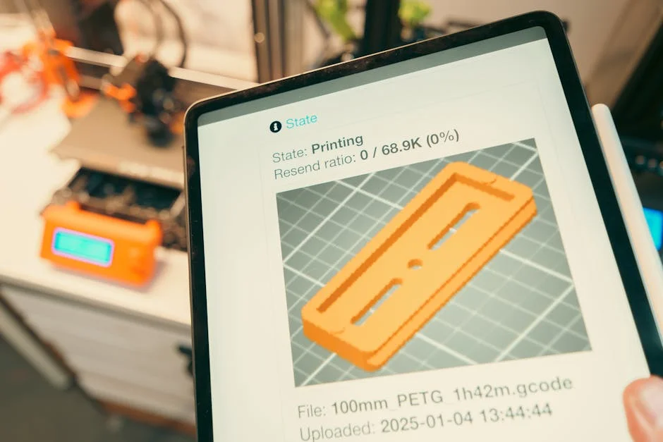
The bridge between tinkercad 3d printing and a successful physical part is the export-and-slice step. Tinkercad commonly exports STL for geometry and OBJ for models that may include color information in some workflows, though most consumer 3D printing pipelines rely on STL. Before exporting, ensure the design is grouped appropriately and that there are no stray shapes hidden inside the model that could create internal voids or confusing surfaces. It’s also wise to position the model so it sits flat on the workplane if you intend to print it that way. While slicers can rotate and reposition models, starting with a clean orientation reduces mistakes. If the model is intended to be printed in multiple pieces, export each component separately to maintain control in the slicer and avoid accidental overlaps.
| Aspect | Tinkercad (for 3D Printing) | Best Use Case |
|---|---|---|
| Ease of use | Beginner-friendly, browser-based drag-and-drop modeling with simple tools and shortcuts. | First-time designers, classrooms, quick edits before printing. |
| Modeling capability | Great for basic shapes, boolean operations, and simple assemblies; limited for complex surfacing/parametric workflows. | Functional prototypes, simple enclosures, name tags, brackets, basic parts. |
| 3D print workflow | Exports STL/OBJ for slicing; you still need a slicer (e.g., Cura/PrusaSlicer) to set supports, infill, and print settings. | Design-to-print pipeline where you model in Tinkercad and finalize print settings in a slicer. |
Expert Insight
In Tinkercad, design for printability by adding generous fillets and chamfers to sharp edges, and keep wall thickness at least 1.2–2.0 mm for most FDM printers. Before exporting, use the Ruler tool to confirm critical dimensions and ensure parts aren’t thinner than your nozzle can reliably print. If you’re looking for tinkercad 3d printing, this is your best choice.
Reduce print failures by orienting your model to minimize overhangs and supports: place the largest flat face on the build plate and split complex shapes into multiple parts using the Workplane and Hole tools, then reassemble with simple alignment features like pegs and sockets. Export as STL, then preview in your slicer to check for non-manifold geometry and confirm layer height, infill, and support settings match the part’s purpose. If you’re looking for tinkercad 3d printing, this is your best choice.
After export, slicer settings determine much of the final quality. Layer height affects surface smoothness and print time; infill affects strength and material use; and wall/perimeter counts determine rigidity and impact resistance. For tinkercad 3d printing, many designs are simple enough that slicer defaults work, but functional parts benefit from deliberate choices. If a bracket needs to withstand load, increase perimeters and consider a stronger infill pattern. If a model has fine details like text, reduce layer height and slow down outer walls. Also pay attention to seam placement and bridging settings, which can affect visible surfaces. When you preview the sliced toolpath, look for thin features that disappear or holes that are filled in; these issues often indicate walls that are too thin or gaps that are below the printer’s resolution. If the slicer preview looks wrong, go back to Tinkercad and adjust geometry rather than trying to “fix it in the slicer.” A reliable workflow treats the slicer as a manufacturing planner, not a geometry editor, keeping the design intent clear and repeatable.
Common Design Mistakes and How to Fix Them in Tinkercad
Many tinkercad 3d printing failures come from a small set of predictable modeling mistakes. One common issue is non-manifold geometry, which can happen when shapes overlap but aren’t grouped, or when holes create thin residual surfaces that confuse slicers. Another frequent problem is designing features smaller than the printer can reproduce, such as 0.2 mm walls on an FDM printer or tiny text that becomes unreadable once sliced. Beginners also tend to ignore chamfers and fillets, leaving sharp internal corners that concentrate stress and cause cracks. Even if the print succeeds, these sharp corners can make parts feel brittle. Tinkercad’s basic shape library can still address this: adding a small cylinder or rounded box at stress points can dramatically improve durability. Misaligned parts are another trap; if two pieces are meant to be symmetrical but were moved by hand, tiny differences can cause uneven walls and weak joints.
Fixing these issues in tinkercad 3d printing usually involves simplifying and re-grouping. If a model behaves strangely, ungroup it and check for accidental holes or hidden shapes. Use the “hide” feature to inspect internal structure and ensure voids are intentional. If small features vanish in the slicer, increase their size or redesign them to be more printer-friendly—for example, use embossed text instead of engraved text on FDM prints, because raised features often survive better than recessed ones. If a part cracks at a corner, redesign with a thicker cross-section and smoother transitions. For alignment problems, rely on the align tool rather than manual dragging, and use the ruler to set exact offsets. If the model is too complex to manage, split it into subassemblies and export them separately. This not only reduces the chance of geometry errors but also improves print success because each piece can be oriented for strength and surface quality. The key is to treat errors as feedback from the manufacturing process and adjust the design in a controlled, measurable way.
Making Functional Parts: Enclosures, Brackets, and Mechanical Fit
tinkercad 3d printing shines when you move beyond figurines and start producing functional parts like enclosures, brackets, and adapters. Enclosures are a great example because they combine many real-world constraints: component clearances, cable routing, fastening methods, and ventilation. A practical enclosure design starts with the internal layout. Place simplified “dummy” shapes representing a circuit board, battery, or sensor, then build walls around them with consistent thickness. Add standoffs for screws by using cylinders and holes sized for your fasteners, and include space for nuts if you plan to capture them inside the plastic. Ventilation can be created with repeated slots using duplication, and cable exits can be made with rounded openings to reduce stress on wires. For lids, consider how you want them to attach: snap-fit for convenience, screws for durability, or friction fit for a quick prototype.
Brackets and mounts are another strong use case for tinkercad 3d printing because they often rely on simple geometry but demand correct dimensions and strength. When designing a bracket, think about load direction and reinforce accordingly. A thin flat plate may flex; adding ribs or a triangular gusset can multiply stiffness with minimal extra material. For holes and slots, remember that FDM prints often need extra clearance. If you want an M3 screw to pass through easily, you may need a 3.2–3.6 mm hole depending on your printer and orientation. For press-fit inserts or heat-set inserts, design the hole to match the insert manufacturer’s recommendation, then print a small test block first to confirm fit. Mechanical fit also includes moving parts: hinges, sliders, and clips. In Tinkercad, you can design these by creating clearances intentionally—using hole shapes to carve space around a pin, for example. Testing small sections before printing a full assembly saves time and helps you dial in reliable tolerances for your specific materials and printer settings.
Improving Print Quality with Orientation, Layer Strategy, and Iteration
Even with a solid design, tinkercad 3d printing results depend heavily on how the part is oriented and how the layers build up. Orientation affects surface finish, strength, and support requirements. A flat face printed on the bed can look smooth, while the same face printed vertically may show layer lines more strongly. Strength is anisotropic in FDM: parts are stronger along the filament path and weaker between layers. If a hook is likely to be pulled, orient it so the layers run along the hook rather than across it. For resin prints, orientation affects suction forces and support placement, which can cause warping or layer separation if ignored. Thinking about orientation while modeling can lead you to add flat reference surfaces or split the model so each piece prints in the best direction.
Iteration is a normal part of tinkercad 3d printing, and treating it as a structured process improves results. When a print fails or doesn’t fit, change one variable at a time: adjust clearance, thicken a wall, or modify an overhang angle. Keep versions of the design so you can revert if a change makes things worse. Layer strategy also matters: increasing perimeters often improves strength more effectively than increasing infill, and adding a few top layers can prevent pillowing on flat surfaces. If you’re chasing a clean look, consider designing features that hide seams, such as placing a seam along a corner or adding a small ridge where a seam line is less visible. For text and logos, orient them so they print on the top surface when possible, where detail is sharpest. A thoughtful combination of design choices, orientation decisions, and controlled iteration turns a basic model into a polished physical object, even when created with a simple toolset.
Classroom, Hobby, and Prototyping Workflows That Scale
tinkercad 3d printing is popular in classrooms and hobby environments because it reduces setup friction, but it can also support surprisingly disciplined prototyping workflows. In education, the browser-based format means students can start modeling quickly, and teachers can focus on design thinking rather than software installation. A scalable classroom workflow often includes standardized project constraints: maximum print size, minimum wall thickness, and a checklist for export readiness. Students can learn to design with manufacturing in mind by printing small prototypes first, then refining based on real measurements. For hobbyists, scaling a workflow means building a personal library of reusable components—like screw bosses, cable clips, and enclosure corners—that can be copied into new projects. This reduces design time and increases reliability because proven geometry is reused rather than reinvented.
For prototyping, tinkercad 3d printing can be paired with a simple validation routine. Start with a minimum viable model that tests the critical fit or function, such as a single corner of an enclosure or a short section of a clamp. Print quickly with draft settings, evaluate, and then refine. Once fit is correct, switch to higher quality settings for the final print. This approach keeps costs low and accelerates learning. Collaboration can also be managed by exporting versions with clear filenames and storing them in shared folders, ensuring everyone prints the same revision. While Tinkercad isn’t a full parametric CAD system, you can simulate a parametric mindset by keeping consistent references, using the ruler for repeatable placement, and building designs from modular subcomponents. These habits make it possible to produce repeatable parts for small projects, club builds, or iterative product concepts without needing heavyweight engineering software.
Final Checks Before Printing and Long-Term Success Tips
Before sending a design to the printer, a short checklist can dramatically improve tinkercad 3d printing success. Confirm the model is correctly sized in millimeters and matches the printer’s build volume. Ensure the object is manifold by grouping intended overlaps and removing stray shapes. Check that walls are thick enough for your nozzle and that small details exceed your printer’s practical resolution. Look for unsupported overhangs that may need redesign or a different orientation. If the part must fit another object, verify critical dimensions with the ruler tool and compare them to caliper measurements. In the slicer, inspect the preview layer-by-layer to catch missing walls, filled holes, and accidental gaps. If something looks suspicious in the preview, it’s usually faster to return to the model and fix geometry than to gamble on a print that may fail.
Long-term improvement in tinkercad 3d printing comes from building a feedback loop between design, slicing, and real-world evaluation. Keep notes on what clearances work for your printer, what hole sizes produce the right screw fit, and what wall thicknesses survive stress. Save small test models that you can reprint after changing filament or resin, because materials vary and can change fit. As you gain experience, aim to design parts that print cleanly without excessive supports, rely on consistent reference dimensions, and use reinforcement where forces concentrate. Over time, the combination of careful measurement, intentional geometry, and iterative refinement will make your prints more predictable and your designs more functional. The most satisfying outcome is when a model goes from concept to a physical object that fits, works, and lasts—exactly the kind of result tinkercad 3d printing can deliver when you design with the process in mind.
Watch the demonstration video
In this video, you’ll learn how to use Tinkercad to design a simple 3D model and prepare it for 3D printing. It covers the basic tools, shaping and resizing objects, aligning parts, and exporting your design as an STL file so it’s ready to slice and print. If you’re looking for tinkercad 3d printing, this is your best choice.
Summary
In summary, “tinkercad 3d printing” is a crucial topic that deserves thoughtful consideration. We hope this article has provided you with a comprehensive understanding to help you make better decisions.
Frequently Asked Questions
What is Tinkercad and how does it relate to 3D printing?
Tinkercad is a free, browser-based 3D design tool that makes it easy to build simple models and export them as STL or OBJ files—perfect for tinkercad 3d printing projects.
How do I export a Tinkercad model for 3D printing?
Open your design in Tinkercad, click **Export**, and choose **STL** (the most common option) or **OBJ**. Once the file downloads, you’re ready to import it into a slicer like **Cura** or **PrusaSlicer** to prep it for **tinkercad 3d printing**.
What settings should I use when exporting from Tinkercad?
Tinkercad exports only the model’s geometry, so for **tinkercad 3d printing** you’ll typically want to export as an STL file. Before you do, double-check that your design is set to the correct dimensions in millimeters so it prints at the size you expect.
Why is my Tinkercad model not manifold or not printable?
Common issues in **tinkercad 3d printing** come from overlapping shapes, accidental internal voids, or parts with zero thickness. To avoid these problems, make sure you’re using **Solid** (not **Hole**) the right way, group your objects carefully, and double-check that every wall and feature has enough thickness to print reliably.
How can I make my Tinkercad design stronger for printing?
For stronger, more reliable results in **tinkercad 3d printing**, try increasing wall thickness, adding fillets or chamfers to reduce stress points, and avoiding thin, tall features that can snap easily. Be sure to design with proper tolerances for fit and movement—and remember that durability also depends heavily on print orientation and infill settings.
How do I ensure parts fit together (tolerances) in Tinkercad?
When designing parts that need to fit together, build in a bit of clearance between the mating surfaces—typically around 0.2–0.5 mm depending on your printer. In **tinkercad 3d printing**, it’s smart to run a few small calibration prints first, then fine-tune the spacing based on how accurately your machine actually prints.
📢 Looking for more info about tinkercad 3d printing? Follow Our Site for updates and tips!

Trusted External Sources
- Tinkercad
Tinkercad is a free, easy-to-use app for 3D design, electronics, and coding.
- TinkerCAD to 3D print – Reddit
Aug 22, 2026 … if you are producing a basic shape through joining other shapes on tinkercad, what are the issues one would face when 3D printing (if using … If you’re looking for tinkercad 3d printing, this is your best choice.
- 3D Design – Tinkercad
Place a ruler to type in exact dimensions and measure the distance between objects for precise 3D printing. … You can even 3D print your creations to bring them … If you’re looking for tinkercad 3d printing, this is your best choice.
- TinkerCad or FreeCad? – Which causes less hair loss? : r/3Dprinting
Feb 21, 2026 … TinkerCad is very easy to learn and very Good for modeling simple objects. With FreeCad you can make more complicated and bigger objects multiple parts, etc. If you’re looking for tinkercad 3d printing, this is your best choice.
- New to SketchUp for 3D printing, only experience Tinkercad
May 4, 2026 … So far, all my design work for **tinkercad 3d printing** has been done in Tinkercad, and it’s the only workflow I really know. Does anyone have tips for making a smooth transition to SketchUp for 3D-printable models?