Fused deposition modeling is one of the most widely recognized approaches to additive manufacturing because it makes 3D printing practical, approachable, and cost-effective across many industries. At its core, the process builds a physical object by depositing molten thermoplastic in a controlled pattern, layer by layer, until the final geometry is complete. The method has become synonymous with desktop 3D printing, but it is also used in professional environments for tooling, jigs and fixtures, concept models, and even end-use parts when the performance requirements align with the materials available. The popularity of fused deposition modeling comes from a combination of straightforward machine architecture, broad material availability, relatively safe handling compared to resin-based systems, and a workflow that can be scaled from hobby use to production farms. While other additive processes may deliver finer detail or different mechanical properties, fused deposition modeling remains a go-to option when speed, affordability, and functional thermoplastic behavior are primary goals.
Table of Contents
- My Personal Experience
- Understanding Fused Deposition Modeling and Why It Matters
- How the FDM Process Works: From Filament to Finished Part
- Key Components of an FDM 3D Printer
- Materials Used in Fused Deposition Modeling
- Design for FDM: Geometry, Orientation, and Support Strategy
- Print Settings That Influence Strength, Accuracy, and Finish
- Common Defects in FDM and How to Prevent Them
- Post-Processing Options for FDM Parts
- Expert Insight
- Applications of Fused Deposition Modeling in Industry
- Quality Control and Repeatability for FDM Production
- Cost Factors: What Drives the Economics of FDM Printing
- Environmental Considerations and Responsible Use
- Future Trends: Where Fused Deposition Modeling Is Headed
- Choosing the Right FDM Setup for Your Goals
- Practical Takeaways for Getting Better Results with Fused Deposition Modeling
- Frequently Asked Questions
My Personal Experience
The first time I used fused deposition modeling, I underestimated how much the setup mattered. I’d designed a simple bracket and hit print, assuming the machine would handle the rest, but the first layer didn’t stick and the whole part turned into a stringy mess around the nozzle. After cleaning the bed, re-leveling it, and slowing the first-layer speed, the next attempt finally laid down clean lines and the print actually finished. What surprised me most was how “mechanical” the learning curve felt—tweaking nozzle temperature, fan settings, and infill like I was tuning a finicky tool rather than just pressing a button. When I snapped the finished bracket into place and it held, it wasn’t perfect-looking, but it felt like I’d earned it.
Understanding Fused Deposition Modeling and Why It Matters
Fused deposition modeling is one of the most widely recognized approaches to additive manufacturing because it makes 3D printing practical, approachable, and cost-effective across many industries. At its core, the process builds a physical object by depositing molten thermoplastic in a controlled pattern, layer by layer, until the final geometry is complete. The method has become synonymous with desktop 3D printing, but it is also used in professional environments for tooling, jigs and fixtures, concept models, and even end-use parts when the performance requirements align with the materials available. The popularity of fused deposition modeling comes from a combination of straightforward machine architecture, broad material availability, relatively safe handling compared to resin-based systems, and a workflow that can be scaled from hobby use to production farms. While other additive processes may deliver finer detail or different mechanical properties, fused deposition modeling remains a go-to option when speed, affordability, and functional thermoplastic behavior are primary goals.
To understand the value of fused deposition modeling, it helps to see it as a manufacturing method rather than a novelty. The same fundamentals that guide injection molding or CNC machining—design intent, material selection, tolerance planning, and quality control—apply here too, but with different constraints and opportunities. Layered deposition makes it possible to create internal channels, lightweight lattice-like structures, and complex shapes that would be expensive or impossible to machine. At the same time, the layer-by-layer nature introduces anisotropy, visible layer lines, and a need to think carefully about print orientation, support strategy, and thermal management. When those factors are managed well, fused deposition modeling can deliver reliable, repeatable results suitable for real-world use, from prototyping a new consumer product enclosure to printing custom fixtures that support an assembly line.
How the FDM Process Works: From Filament to Finished Part
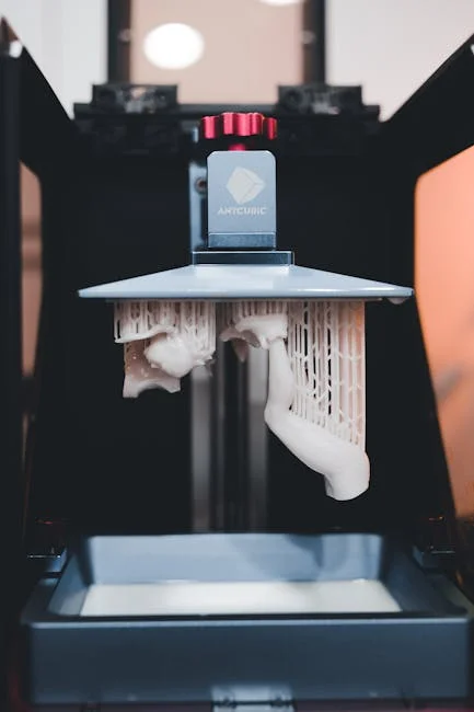
The fused deposition modeling workflow begins with a digital 3D model, typically created in CAD software, which is exported into a triangulated mesh format such as STL or 3MF. Slicing software then translates that geometry into toolpaths: the specific routes the printer’s nozzle will follow, along with settings for layer height, extrusion width, temperatures, speeds, cooling, and support generation. During printing, filament is driven by gears into a heated hotend where it softens and becomes viscous. The printer deposits this material through a nozzle, laying down roads of plastic that fuse to the layer below. Each layer is created by a combination of perimeter walls (shells) and internal infill patterns. Over time, the build plate moves down (or the print head moves up, depending on machine design) to make room for the next layer. This incremental stacking is what gives fused deposition modeling its distinctive look and its unique mechanical behavior.
Although the concept sounds simple, consistent results require balancing multiple variables. The hotend must maintain a stable melt zone so extrusion is predictable, while the motion system must position the nozzle accurately at speed. Cooling is equally important: too little airflow can cause sagging bridges, drooping overhangs, and poor detail, while too much can reduce layer adhesion and cause warping on materials that shrink. Bed adhesion is another cornerstone of fused deposition modeling reliability. A part that lifts at the corners can ruin dimensional accuracy and may lead to a failed print if the nozzle collides with the warped section. Operators often use textured build surfaces, adhesives, or carefully tuned first-layer settings to secure parts. When these elements—slicing, extrusion, motion, cooling, and adhesion—work together, fused deposition modeling becomes a dependable manufacturing tool rather than a trial-and-error exercise.
Key Components of an FDM 3D Printer
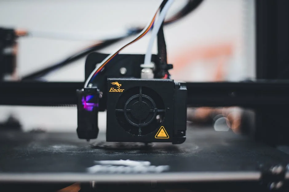
A fused deposition modeling printer is essentially a coordinated system of mechanical, thermal, and electronic subsystems designed to move a nozzle precisely while controlling material flow. The extrusion system typically includes a drive mechanism (direct drive or Bowden), the hotend, and the nozzle. Direct drive places the filament drive close to the hotend, improving control for flexible materials and reducing retraction issues, while Bowden setups reduce moving mass on the toolhead, which can help with speed and ringing control. The hotend contains a heat break, heater block, temperature sensor, and nozzle; it must provide enough heat to melt filament consistently without allowing heat creep that softens filament too high up and causes jams. Nozzle diameter affects detail, print time, and strength; common sizes like 0.4 mm are versatile, while larger nozzles improve throughput for functional parts.
Beyond the extrusion path, the motion system defines how accurately fused deposition modeling can place material. Many machines use Cartesian kinematics with belts and stepper motors, while others use CoreXY or delta designs. Linear rails, quality belts, and rigid frames reduce vibration and improve dimensional accuracy. The build platform is another critical component: heated beds reduce warping by keeping the first layers above the glass transition temperature for longer, allowing stresses to relax. Enclosures help with temperature stability for materials like ABS, ASA, and nylon, which can crack or warp in drafts. Electronics and firmware control acceleration, jerk, pressure advance, input shaping, and thermal safety. Modern printers also incorporate sensors for filament runout, automatic bed leveling, and sometimes nozzle pressure monitoring. Each component choice influences the range of materials, the level of repeatability, and the overall capability of fused deposition modeling in a given environment.
Materials Used in Fused Deposition Modeling
Material choice is one of the biggest reasons fused deposition modeling is so widely adopted. Common entry-level filaments include PLA, known for ease of printing, low warping, and good surface finish. PLA is often used for visual models, fixtures with light loads, and educational projects, but it can soften at relatively low temperatures and may be brittle depending on formulation. PETG offers improved toughness and better temperature resistance than PLA, with good layer adhesion and chemical resistance, though it can be stringy and may require tuning retraction and cooling. ABS and ASA provide higher heat resistance and impact performance, making them suitable for enclosures, automotive-adjacent parts, and outdoor use in the case of ASA, which is more UV-stable. These materials can warp, so fused deposition modeling printers often need heated beds and enclosures to print them reliably.
Engineering-grade filaments expand what fused deposition modeling can do in functional manufacturing. Nylon (polyamide) is valued for toughness and fatigue resistance, but it is hygroscopic and needs dry storage and often a hardened nozzle if filled. Polycarbonate offers high strength and heat resistance but can be challenging due to warping and the need for high temperatures. TPU and other flexible filaments enable gaskets, grips, and vibration dampers, benefiting from direct-drive extrusion. Composite filaments—such as carbon fiber-filled PETG, nylon, or polycarbonate—can improve stiffness and reduce warping, but they are abrasive and require hardened nozzles and often hardened drive gears. Specialty materials include ESD-safe blends for electronics handling, flame-retardant filaments for regulated applications, and soluble supports like PVA or BVOH for complex geometries. With the right machine configuration, fused deposition modeling can cover a wide spectrum of mechanical and environmental requirements.
Design for FDM: Geometry, Orientation, and Support Strategy
Designing parts for fused deposition modeling involves thinking in layers. Overhangs beyond a certain angle—often around 45 degrees—may require support material, which increases print time and post-processing. Bridges can span gaps if cooling and extrusion are tuned, but long bridges may sag. Designers can reduce supports by adding chamfers, fillets, and self-supporting angles, or by splitting a model into multiple pieces that print flat and then assemble with fasteners or adhesives. Wall thickness should align with nozzle width and perimeter counts; for example, a 0.4 mm nozzle often produces best results when wall thickness is a multiple of the extrusion width used by the slicer. Features like holes and slots may print undersized due to material shrinkage and toolpath approximations, so design allowances and calibration are important for accurate fits.
Print orientation is one of the most important decisions in fused deposition modeling because it affects strength, surface quality, and dimensional accuracy. Parts are typically stronger along the direction of the extruded roads and weaker across layer boundaries, so a load-bearing feature should be oriented so the primary stress aligns with the strongest direction when possible. For example, a hook printed standing up may snap along layer lines, while the same hook printed on its side can be significantly stronger. Orientation also determines where supports touch the surface and where layer lines are most visible. If a cosmetic face must look smooth, it may be oriented upward or printed against a textured build plate. For threaded features, designers might use heat-set inserts or print threads with generous profiles. By combining thoughtful geometry, strategic orientation, and support planning, fused deposition modeling can produce parts that are both functional and visually acceptable with minimal post-processing.
Print Settings That Influence Strength, Accuracy, and Finish
Slicer settings are the control panel for fused deposition modeling performance. Layer height affects surface finish and print time; smaller layers can capture more detail and reduce the “stair-step” effect on curved surfaces, but they increase the number of layers and can amplify issues like heat buildup on small features. Extrusion temperature influences layer adhesion and surface quality. Too low and layers may not fuse well, leading to weak parts; too high and the print can string, blob, or lose detail. Print speed and acceleration affect how well the printer can follow corners and maintain consistent extrusion; pushing speed too far can cause under-extrusion, ringing, or poor layer stacking if the hotend cannot melt filament fast enough. Cooling settings can improve bridging and overhangs but may reduce interlayer bonding on materials that benefit from slower cooling.
Strength in fused deposition modeling is also strongly influenced by perimeters, infill, and top/bottom layers. Increasing the number of perimeter walls often boosts strength more efficiently than raising infill percentage, especially for parts that experience bending or impact. Infill patterns like gyroid or cubic can provide isotropic support and good strength-to-weight ratios, while rectilinear patterns are fast and predictable. Top and bottom thickness prevents pillowing and improves surface integrity. Retraction settings help reduce stringing but can cause jams or under-extrusion if too aggressive, particularly with softer materials. Dimensional accuracy depends on careful calibration: steps-per-mm (or equivalent motion calibration), flow rate, temperature stability, and first-layer squish. Many operators use test prints to tune these factors for each material. When settings are matched to the part’s purpose—cosmetic model, functional bracket, or precision jig—fused deposition modeling becomes far more consistent and repeatable.
Common Defects in FDM and How to Prevent Them
Even well-tuned fused deposition modeling systems can experience print defects, but most issues have identifiable causes and practical solutions. Warping is a frequent challenge, especially with materials that shrink as they cool. It often shows up as corners lifting from the bed, leading to distorted dimensions and poor layer alignment. Solutions include a heated bed, enclosure, better bed surface preparation, larger brims, and adjusting first-layer height and speed. Layer shifting can occur when belts are loose, pulleys slip, or the printer experiences collisions with curled edges; ensuring proper belt tension, stable wiring, and adequate stepper current can help. Under-extrusion may be caused by partial nozzle clogs, low temperature, incorrect filament diameter settings, or a slipping extruder gear. Regular maintenance and keeping filament dry can prevent many extrusion problems.
Surface artifacts are also common in fused deposition modeling. Stringing and oozing often result from high temperature, insufficient retraction, or wet filament that releases steam bubbles. Blobs and zits can come from inconsistent extrusion, pressure changes at corners, or poorly configured seam placement; features like pressure advance and seam hiding can reduce these marks. Poor overhang quality may be improved with better part cooling, slower speeds on overhangs, and redesigned geometry that avoids unsupported angles. Delamination—layers separating under stress—usually points to low temperature, excessive cooling, or drafts, and it is especially relevant for ABS and nylon. Elephant’s foot, where the first layers bulge outward, can be reduced by lowering bed temperature after the first layers, reducing first-layer squish, or adding a chamfer to the model. With a structured troubleshooting approach, fused deposition modeling defects become manageable rather than mysterious.
Post-Processing Options for FDM Parts
Post-processing can elevate fused deposition modeling parts from “printed” to “production-ready,” depending on requirements. Basic steps include removing supports, trimming strings, and lightly sanding surfaces. Support removal can be simple when using breakaway supports, but complex geometries may benefit from soluble support materials that dissolve in water or specialized solutions, leaving cleaner surfaces in hard-to-reach areas. Sanding can reduce layer lines, but it is labor-intensive and may soften edges if too aggressive. For many functional components, minimal post-processing is preferred to preserve dimensional accuracy. However, when a part must look refined, a combination of sanding, filler primer, and paint can create a smooth finish suitable for presentation models or consumer-facing prototypes.
| Aspect | What it means in Fused Deposition Modeling (FDM) | Practical impact |
|---|---|---|
| Materials | Thermoplastic filament is heated and extruded through a nozzle (e.g., PLA, ABS, PETG, TPU). | Wide material choice and low cost; properties vary from rigid to flexible, but high-temp/engineering performance may require specialized filaments. |
| Surface finish & detail | Parts are built layer-by-layer, typically leaving visible layer lines and limited fine feature resolution vs. resin-based methods. | Good for prototypes and functional parts; may need sanding, vapor smoothing, or coating for cosmetic surfaces and tight tolerances. |
| Speed, cost & scalability | Relatively inexpensive printers and consumables; print time depends on layer height, infill, and part geometry. | Cost-effective for iteration and small-batch production; large or high-detail prints can be slow, and support removal adds labor. |
Expert Insight
Calibrate first, then print: level the bed, set the correct Z-offset, and run a temperature tower for each filament brand to lock in layer adhesion and surface finish. Once dialed in, save profiles for common materials (PLA, PETG, ABS) so repeat jobs start with proven settings. If you’re looking for fused deposition modeling, this is your best choice.
Design for the process: orient parts so critical faces print upward, add chamfers to reduce elephant’s foot, and use 3–5 perimeters with 15–30% infill for strong, efficient prints. For overhangs, keep angles under ~45°, use supports only where necessary, and add small fillets or ribs instead of relying on high infill for strength. If you’re looking for fused deposition modeling, this is your best choice.
For certain plastics, chemical smoothing is an option, though it requires careful handling and appropriate ventilation. ABS can be vapor-smoothed using solvents that slightly melt the surface, blending layer lines into a glossy finish. This can improve aesthetics and sometimes reduce surface porosity, but it can also soften sharp details and slightly alter dimensions. Mechanical finishing methods include tumbling for small parts, machining critical surfaces, drilling holes to final size, and tapping threads. Heat-set inserts are widely used in fused deposition modeling to create durable threaded connections in thermoplastics, enabling repeated assembly and disassembly. Bonding methods include cyanoacrylate glues for quick joins and solvent welding for compatible plastics. With the right post-processing plan, fused deposition modeling parts can meet demanding expectations for fit, appearance, and assembly performance.
Applications of Fused Deposition Modeling in Industry
Fused deposition modeling is used across industries because it bridges the gap between rapid prototyping and practical manufacturing. Product development teams rely on it to iterate quickly on form and fit, producing multiple design variants in days rather than waiting for outsourced prototypes. Engineers use it to validate ergonomics, assembly clearances, cable routing, and enclosure layouts before committing to expensive tooling. In manufacturing environments, fused deposition modeling is commonly used to create jigs, fixtures, and gauges that improve repeatability and reduce operator fatigue. These tools can be customized to a specific workstation, updated when a process changes, and produced on demand, reducing downtime. Because thermoplastics have a degree of toughness and chemical resistance, many printed tools hold up well in real production settings when designed with appropriate safety factors.
Beyond tooling, fused deposition modeling supports low-volume production and mass customization. Medical and dental contexts use printed models, guides, and custom-fit components where regulations and material qualifications permit. Education and research labs use the process to build experimental apparatus, housings for sensors, and prototypes for robotics. In architecture and construction-related design, it produces scaled models and complex geometric studies. In automotive and aerospace supply chains, it is used for prototyping and for non-critical interior components, brackets, and protective covers, especially when weight reduction and fast turnaround are valuable. Print farms—arrays of printers managed as a production system—have made fused deposition modeling a viable way to produce hundreds or thousands of parts when the design is optimized for printing and quality control is disciplined.
Quality Control and Repeatability for FDM Production
Using fused deposition modeling for production requires a different mindset than using it for occasional prototyping. Repeatability starts with standardizing machines, materials, and profiles. Consistent filament diameter, tight material tolerances, and controlled moisture levels reduce variability in extrusion and surface quality. Many production environments store filament in dry boxes and use inline drying for hygroscopic materials like nylon and TPU. Machine calibration must be documented: bed leveling routines, nozzle offsets, extrusion flow calibration, and temperature verification. Preventive maintenance schedules—replacing nozzles, cleaning drive gears, checking belts, and inspecting fans—keep the process stable over time. When multiple printers are used, matching hardware configurations and firmware settings helps ensure that a part printed on one machine matches a part printed on another.
Inspection methods for fused deposition modeling vary by application. For simple parts, visual inspection and basic dimensional checks with calipers may be sufficient. For more demanding uses, organizations may implement go/no-go gauges, coordinate measuring machine (CMM) checks on critical features, or functional testing under load. Process monitoring can include tracking print parameters, using cameras to detect failures, and logging temperatures and job histories for traceability. Statistical process control principles can be applied to key dimensions to detect drift. Batch labeling and material lot tracking become important when parts are used in assemblies or shipped to customers. While fused deposition modeling is inherently more variable than some traditional manufacturing processes, disciplined controls can bring it to a level of reliability that supports real production needs.
Cost Factors: What Drives the Economics of FDM Printing
The economics of fused deposition modeling are shaped by a combination of capital cost, material cost, labor, and time. Desktop printers can be inexpensive, but professional systems with enclosures, higher-temperature capabilities, and robust motion components cost more upfront. Material cost varies widely: standard PLA may be relatively cheap per kilogram, while specialty filaments like carbon fiber-filled nylon or ESD-safe blends can be significantly more expensive. Print time is a major driver because it affects throughput and energy use. A part that takes 18 hours ties up a machine and may require supervision or at least monitoring, whereas a redesigned part that prints in 6 hours can triple output capacity. Slicer choices—layer height, infill, supports—directly influence these time and material costs.
Labor is often underestimated in fused deposition modeling. Preparing builds, swapping filament, removing parts, cleaning beds, post-processing, and inspecting parts can add substantial time per unit, especially when supports are heavy or surface finishing is required. Design optimization can reduce labor by minimizing supports, avoiding fragile features, and using self-jigging geometries that assemble easily. Another cost consideration is print failure rate, which can be reduced through better materials handling, machine maintenance, and validated profiles. For businesses, it helps to calculate cost per part using a consistent model: material used, machine time valued at an hourly rate, labor minutes, and a factor for overhead and scrap. When these elements are controlled, fused deposition modeling can be one of the most economical ways to produce functional plastic parts in low to medium volumes.
Environmental Considerations and Responsible Use
Fused deposition modeling can support more sustainable workflows when used thoughtfully, but it also introduces environmental considerations that should be managed. On the positive side, additive manufacturing can reduce waste compared to subtractive methods because material is placed only where needed, and infill can reduce total plastic usage while maintaining functional performance. Local, on-demand production can reduce shipping and packaging for certain use cases, especially for spare parts and custom tools. However, failed prints, support material, and iteration cycles can create significant plastic waste if processes are not optimized. Selecting designs that minimize supports, validating settings with small test coupons, and using reliable profiles can reduce scrap. Some filaments are marketed as biodegradable, but real-world biodegradation depends on industrial composting conditions, so disposal should still be considered carefully.
Air quality is another factor in fused deposition modeling environments. Heating thermoplastics can release ultrafine particles and volatile organic compounds, with emission profiles varying by material. Good ventilation, filtration, and enclosures can reduce exposure, particularly in classrooms, offices, or print farm settings. Energy consumption is influenced by heated beds, enclosures, and long print times; efficient scheduling and printing multiple parts per run can reduce energy per unit. Responsible material storage also matters: keeping filament dry prevents waste from poor print quality and reduces the need to discard moisture-damaged spools. Recycling options for printed parts and supports remain limited in many locations due to mixed materials and contamination, but some organizations implement take-back programs or dedicated recycling streams for specific polymers. With sensible controls, fused deposition modeling can be integrated into a responsible manufacturing strategy rather than adding avoidable waste.
Future Trends: Where Fused Deposition Modeling Is Headed
Fused deposition modeling continues to evolve through improvements in hardware, software, and materials. On the hardware side, faster motion systems, better vibration control, and smarter extrusion management are enabling higher speeds without sacrificing quality. Features like input shaping, pressure advance, and advanced path planning reduce ringing and improve corner sharpness, making prints look cleaner at higher throughput. Multi-material printing is becoming more accessible, allowing combinations such as rigid and flexible sections, multiple colors, or dedicated support materials that remove cleanly. High-temperature printers expand the usable material set to include more engineering polymers, which increases the range of functional applications. As reliability improves, fused deposition modeling becomes less about constant tuning and more about predictable manufacturing outcomes.
Software and workflow automation are also reshaping fused deposition modeling. Slicers are getting better at generating strong toolpaths, optimizing seam placement, and creating supports that are easier to remove. Fleet management tools help coordinate print farms, track job status, and maintain consistent profiles across machines. On the materials side, new blends aim to improve layer adhesion, reduce warping, and provide specific properties like conductivity, flame resistance, or enhanced toughness. There is also growing interest in validation and certification pathways for printed parts, especially in regulated industries, which could broaden adoption for more critical components. Even as other additive technologies grow, fused deposition modeling remains central because it is adaptable, scalable, and continually improving in ways that make practical manufacturing easier for more organizations.
Choosing the Right FDM Setup for Your Goals
Selecting a fused deposition modeling setup depends on the types of parts you need, the materials you plan to use, and the level of throughput required. For basic prototypes and visual models, a reliable open-frame printer with a heated bed may be sufficient, especially if you primarily print PLA or PETG. If you need ABS, ASA, nylon, or polycarbonate, an enclosed printer with higher nozzle and bed temperatures becomes far more important for consistency. For abrasive composite filaments, hardened steel or tungsten carbide nozzles and hardened drive components reduce wear and maintain dimensional consistency over time. Consider build volume based on the largest part you expect to print, but also remember that larger machines can be harder to keep thermally stable. Precision features like automatic bed leveling and filament runout detection can reduce failures and improve day-to-day usability.
Workflow considerations can matter as much as hardware. A fused deposition modeling process that is easy to repeat—standard profiles, documented settings, controlled filament storage, and routine maintenance—often outperforms a more expensive machine that is not managed carefully. If production is a goal, think about how parts will be removed, how beds will be reset, and how prints will be monitored. A flexible system for labeling parts, tracking revisions, and inspecting key dimensions can prevent costly mix-ups. It also helps to align expectations with the process: fused deposition modeling excels at functional plastic parts with visible layer lines, but if you need injection-mold-like cosmetics straight off the printer, post-processing or a different technology may be required. When machine choice, materials, and workflow are matched to the application, fused deposition modeling delivers a highly competitive balance of cost, speed, and capability.
Practical Takeaways for Getting Better Results with Fused Deposition Modeling
Strong results with fused deposition modeling come from combining good design habits with stable process control. Start with dry, consistent filament and store spools properly, especially for nylon, PETG, and TPU. Use a proven slicer profile for each material and change one variable at a time when tuning. Pay special attention to the first layer: clean the build surface, confirm bed leveling, and use appropriate first-layer speed and temperature to build a foundation that won’t lift mid-print. Choose print orientation based on load paths and surface requirements, not just convenience, and consider adding chamfers, ribs, and fillets to strengthen parts without excessive material. If a part must be assembled repeatedly, use heat-set inserts rather than relying on printed threads alone. These habits reduce failures, improve mechanical performance, and make prints more predictable.
As needs grow, treat fused deposition modeling like a manufacturing process with documentation and feedback loops. Keep notes on successful profiles, nozzle sizes, and material lots, and schedule maintenance so quality doesn’t drift. Use simple test coupons to validate dimensional accuracy before committing to long builds, and design parts to minimize supports and post-processing where possible. When surface finish matters, plan for sanding, priming, or chemical smoothing rather than expecting perfect cosmetics directly from the printer. Most importantly, match the material to the environment the part will face—heat, UV, chemicals, and mechanical load—so performance is dependable. With these principles in place, fused deposition modeling remains one of the most versatile and cost-effective ways to turn digital designs into real, usable objects, and it continues to earn its role as a cornerstone of modern additive manufacturing.
Summary
In summary, “fused deposition modeling” is a crucial topic that deserves thoughtful consideration. We hope this article has provided you with a comprehensive understanding to help you make better decisions.
Frequently Asked Questions
What is fused deposition modeling (FDM)?
FDM is a 3D printing process that melts and extrudes thermoplastic filament through a nozzle, depositing material layer by layer to build a part.
What materials can be used in FDM printing?
Popular 3D printing filaments include PLA, ABS, PETG, TPU, nylon, and composite blends like carbon-fiber-filled materials. In **fused deposition modeling**, the material you choose directly influences a part’s strength, heat resistance, flexibility, and how smoothly it prints.
How accurate and detailed are FDM prints?
Most prints use layer heights of about 0.1–0.3 mm, and with **fused deposition modeling**, you can typically expect dimensional accuracy around ±0.2 mm or ±0.2% depending on the printer and how it’s set up. Just keep in mind that very fine features are constrained by the nozzle diameter and the visible layer lines inherent to the process.
Why do FDM prints warp or detach from the build plate?
Warping is most often caused by uneven cooling and the resulting shrinkage—especially when printing ABS or nylon with **fused deposition modeling**. To prevent it, focus on improving bed adhesion, dialing in your bed and nozzle temperatures, printing in an enclosure to keep heat consistent, and minimizing drafts or sudden airflow around the printer.
What are supports in FDM and when are they needed?
Support structures are temporary features printed to prop up overhangs and bridges during **fused deposition modeling**. They become necessary when a design extends beyond what the printer can handle without backing—often anything steeper than about a 45° overhang—and are removed once the print is finished.
How can I improve FDM part strength?
To make your parts tougher, increase the wall/perimeter count and use a higher infill percentage only where extra strength is needed. In **fused deposition modeling**, you’ll also get better results by optimizing print orientation so the layer lines align with the forces the part will face, and by improving layer adhesion through the right temperature and cooling settings. Finally, consider switching to stronger filaments such as PETG or nylon for a noticeable boost in durability.
📢 Looking for more info about fused deposition modeling? Follow Our Site for updates and tips!