CAD 3D printing sits at the intersection of digital precision and real-world manufacturing, turning a computer-based model into a tangible object through additive processes. The phrase “CAD” refers to computer-aided design, a workflow that allows you to define geometry, dimensions, tolerances, and features with far more control than sketching or sculpting by hand. When that design is prepared correctly, CAD 3D printing can produce prototypes, end-use parts, jigs, fixtures, and customized products with impressive speed. The core value comes from the way a CAD model describes an object as a set of measurable surfaces or volumes, which can then be converted into printable data. Unlike subtractive methods that carve away material, additive manufacturing builds layer by layer, meaning design intent and print constraints must align. A strong CAD approach anticipates layer direction, overhangs, support requirements, and the limits of a chosen printer, whether it’s an FDM desktop machine or an industrial resin or powder system. The better the design understands the printing process, the less time gets wasted on failed builds, warped parts, or components that look right on screen but do not function in the real world.
Table of Contents
- My Personal Experience
- Understanding CAD 3D Printing: Where Digital Design Meets Physical Output
- Choosing the Right CAD Approach for Additive Manufacturing
- Designing for Printability: Geometry Rules That Prevent Failures
- From CAD Model to Printable File: Mesh Export and Data Integrity
- Slicing Strategy and How CAD Decisions Influence Toolpaths
- Material-Aware CAD: Designing Differently for PLA, PETG, ABS, Resin, and More
- Functional Tolerances, Fits, and Assemblies in CAD 3D Printing
- Expert Insight
- Optimizing Strength: Ribs, Fillets, Lattice, and Topology-Aware Modeling
- Workflow Efficiency: Parametric Templates, Libraries, and Reusable Features
- Common Mistakes and How to Avoid Them in CAD for Additive Manufacturing
- Future-Proofing Designs: Interoperability, Collaboration, and Emerging Standards
- Practical Applications: Prototyping, Production, Education, and Customization
- Building a Reliable End-to-End Process for CAD 3D Printing
- Watch the demonstration video
- Frequently Asked Questions
- Trusted External Sources
My Personal Experience
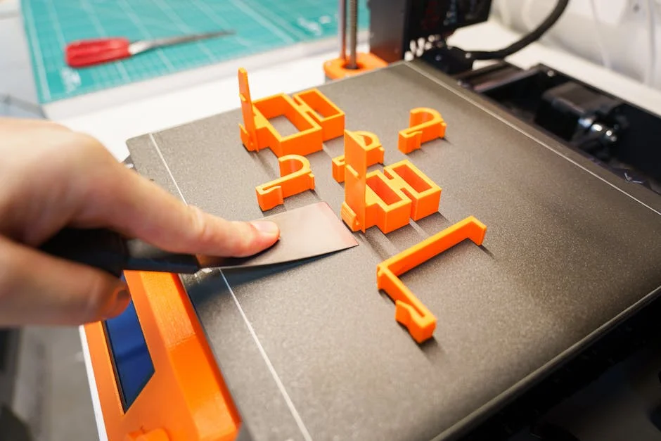
The first time I tried CAD for 3D printing, I assumed if the model looked fine on my screen it would print fine too. I designed a small cable clip in Fusion 360, exported an STL, and hit print—only to watch it snap the moment I flexed it. After a bit of trial and error, I realized my walls were too thin and I hadn’t accounted for layer direction, so I went back, added fillets, bumped the thickness from 1 mm to 2.4 mm, and oriented it so the stress ran along the layers instead of across them. The next print came off the bed cleanly and actually worked, which was a surprisingly satisfying moment. Now I always do a quick check for tolerances, overhangs, and weak points before exporting, because the printer is brutally honest about every shortcut you take in CAD. If you’re looking for cad 3d printing, this is your best choice.
Understanding CAD 3D Printing: Where Digital Design Meets Physical Output
CAD 3D printing sits at the intersection of digital precision and real-world manufacturing, turning a computer-based model into a tangible object through additive processes. The phrase “CAD” refers to computer-aided design, a workflow that allows you to define geometry, dimensions, tolerances, and features with far more control than sketching or sculpting by hand. When that design is prepared correctly, CAD 3D printing can produce prototypes, end-use parts, jigs, fixtures, and customized products with impressive speed. The core value comes from the way a CAD model describes an object as a set of measurable surfaces or volumes, which can then be converted into printable data. Unlike subtractive methods that carve away material, additive manufacturing builds layer by layer, meaning design intent and print constraints must align. A strong CAD approach anticipates layer direction, overhangs, support requirements, and the limits of a chosen printer, whether it’s an FDM desktop machine or an industrial resin or powder system. The better the design understands the printing process, the less time gets wasted on failed builds, warped parts, or components that look right on screen but do not function in the real world.
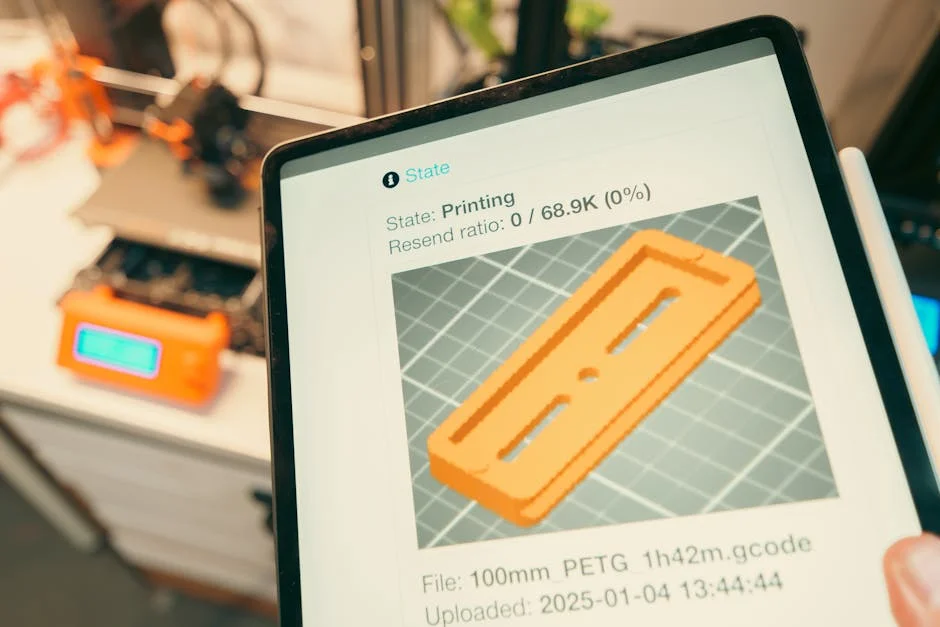
Successful CAD 3D printing also depends on understanding how the digital model becomes machine instructions. Most printers cannot read native CAD files directly; instead, the model is exported as a mesh or manufacturing file, then sliced into toolpaths. That translation introduces practical issues: mesh resolution can add faceting, thin walls can disappear, and non-manifold edges can confuse slicers. A designer who treats CAD as “just making a shape” often runs into problems later, while a designer who treats CAD as an engineering description tends to get repeatable results. Material choice further affects design strategy: plastics shrink and creep, resins can be brittle, and metals require different allowances. Even when the part is purely aesthetic, the CAD model must still be watertight and printable. CAD 3D printing becomes far more reliable when the CAD stage includes print-aware decisions such as minimum wall thickness, chamfers to reduce elephant’s foot, fillets to strengthen corners, and clearance for moving assemblies.
Choosing the Right CAD Approach for Additive Manufacturing
Different CAD methods produce different strengths, and selecting the right approach improves CAD 3D printing outcomes. Parametric solid modeling, common in tools like Fusion, SolidWorks, Onshape, and Inventor, is ideal for functional parts that need precise dimensions and iterative changes. Parametric workflows let you define sketches, constraints, and features such as extrudes, revolves, lofts, and patterns, then adjust dimensions later without rebuilding from scratch. That’s powerful for enclosures, brackets, mounts, gears, and fixtures where hole sizes, clearances, and alignment matter. Direct modeling, in contrast, can feel more flexible for quick modifications or imported geometry, letting you push/pull faces without a strict history timeline. For CAD 3D printing, direct editing is useful when you’re repairing a model from a vendor or adapting a downloaded part to a specific printer or application. Surface modeling becomes important when aesthetics and smooth transitions matter—consumer product shells, ergonomic grips, and organic curves benefit from surface tools that create continuous curvature rather than blocky solids.
Another common route is sculpting or subdivision modeling, often found in tools like Blender, ZBrush, or Fusion’s Form environment. These can generate highly organic shapes, miniatures, and artistic pieces, but they typically produce mesh-based geometry rather than precise parametric solids. That can still work well for CAD 3D printing if the model is clean, manifold, and appropriately detailed, but functional tolerances are harder to control. A hybrid workflow is common: sculpt the exterior form, then convert to a solid and add engineered features such as bosses, screw posts, snap fits, and alignment pins. The “right” CAD method depends on the end goal: a mechanical replacement part benefits from parametric constraints and measured features, while a figurine benefits from sculpting and controlled mesh density. Matching the CAD strategy to the printer and material is equally important. A resin printer can capture fine textures that an FDM printer will blur; designing tiny embossed text for FDM often fails, while it can look crisp in SLA. CAD 3D printing improves when the design environment and modeling style are chosen with the target process in mind rather than personal habit alone.
Designing for Printability: Geometry Rules That Prevent Failures
Printability is the discipline of shaping geometry so that it can be produced reliably, and it is a defining skill in CAD 3D printing. Many failed prints can be traced to a few predictable issues: walls that are too thin, unsupported overhangs, large flat areas that warp, sharp corners that concentrate stress, or details smaller than the nozzle or pixel size. A print-ready CAD model typically uses minimum wall thickness guidelines based on material and process. For FDM, a practical rule is to keep walls at least 0.8–1.2 mm for small parts and 1.6–2.4 mm for larger components, depending on nozzle size and intended strength. For resin printing, walls can be thinner, but suction forces and brittleness become concerns, so hollow parts need drainage, vent holes, and ribs. For powder-bed processes, thin walls may sinter poorly or distort during depowdering. Adding fillets and ribs can transform a fragile design into a durable one without adding much material. Chamfers on the bottom edges can reduce the “elephant’s foot” effect common in FDM, where the first layers spread slightly due to heat and bed pressure.
Overhang management is another key area. In CAD 3D printing, designing to avoid supports often yields better surface finish and saves time. Angles below about 45 degrees from vertical are generally easier for FDM, while resin can handle different angles but may need supports to prevent peel forces and deformation. Bridging spans should be kept within the printer’s capability, and long horizontal features may benefit from arches, teardrop holes, or self-supporting geometry. Hole design deserves special care: printed holes often come out undersized, especially in FDM, because the extrusion path approximates circles and plastic shrinks. Designers often oversize holes slightly or plan to drill/ream them post-print. For assemblies, clearance is essential. A sliding fit might need 0.2–0.4 mm clearance in resin and 0.3–0.6 mm or more in FDM, depending on machine tuning. Snap fits require flexible materials and thoughtful stress relief, such as fillets at the base of cantilever arms. These geometry considerations are not abstract theory; they are the difference between a model that looks perfect on screen and a part that actually prints, assembles, and survives use.
From CAD Model to Printable File: Mesh Export and Data Integrity
The transition from a CAD model to a printable file is where many CAD 3D printing projects succeed or fail. Most workflows export to STL, 3MF, or OBJ, with STL still common but limited because it carries only triangulated geometry and no units or metadata. 3MF is increasingly preferred because it can store units, color, materials, and multiple parts in a single package, reducing scaling errors and preserving intent. Export settings matter: a coarse mesh can create visible faceting on curves and circles, while an overly fine mesh can produce huge files that slow slicing without improving print quality beyond the printer’s resolution. A balanced approach uses tighter tolerance for functional curved surfaces and looser tolerance for flat areas. Many CAD packages allow you to set chord height and angular tolerance; lowering chord height increases fidelity but also increases triangle count. The goal is to make the mesh smooth relative to the printer’s capabilities. For example, if an FDM printer’s XY accuracy is around 0.1–0.2 mm, exporting a mesh with microscopic triangles may be pointless.
Data integrity also includes ensuring the model is watertight (manifold) and free of self-intersections. Non-manifold edges, internal faces, and open shells can confuse slicers, leading to missing layers, holes, or odd toolpaths. CAD systems usually produce clean solids, but problems arise when models are imported from meshes or when multiple bodies intersect without being properly combined. Boolean operations should be validated, and the final body should be a single solid when appropriate. If you are exporting an assembly, consider whether it should be printed as separate parts or as an articulated print-in-place mechanism. Print-in-place designs require careful clearance and orientation planning to avoid fused joints. If you rely on mesh repair tools, use them thoughtfully: automatic fixes can close intended openings or distort critical features. A more reliable path is to correct the design at the CAD level, then export again. CAD 3D printing becomes a predictable process when the export step is treated as a controlled manufacturing handoff rather than a quick “save as STL” afterthought.
Slicing Strategy and How CAD Decisions Influence Toolpaths
Slicing converts a printable file into layers and toolpaths, and CAD 3D printing outcomes depend heavily on how the slicer interprets the model. Layer height, wall count, infill strategy, seam placement, and support generation all interact with geometry. CAD choices can either make slicing straightforward or create complicated edge cases. For instance, if a wall thickness is not a multiple of extrusion width, the slicer may create gaps, thin “single-line” walls, or inconsistent perimeters. Designing walls with standard extrusion widths in mind—such as 0.4 mm nozzle with 0.45 mm line width—can produce stronger, cleaner parts. Similarly, tiny features may be ignored if they are below the minimum feature size; embossed text may vanish or turn into blobs if strokes are too thin. Adding draft angles or simplifying micro-details can yield better real-world fidelity. For resin printing, thin spikes and long cantilevers can wobble during peel, so CAD changes like thickening, adding fillets, or splitting into parts can prevent failures that no slicer setting can fully solve.
Orientation is another area where CAD and slicing meet. A part can be oriented for strength, surface finish, or speed, but rarely all three at once. In FDM, strength is weakest between layers, so load-bearing parts should often be oriented so that layer lines run along the direction of stress rather than across it. CAD can help by allowing you to split a part into multiple pieces so each prints in an optimal orientation, then assemble them with dovetails, pins, or screws. Surface finish considerations often suggest placing visible surfaces upward or away from supports. CAD can incorporate sacrificial features—support blockers, chamfers, or “mouse ears” for bed adhesion—that are later removed. In resin printing, orientation is about minimizing suction and support marks; adding flat surfaces parallel to the build plate can cause cupping forces and failures, so hollowing and venting may be required. When CAD 3D printing is treated as a full pipeline, the designer anticipates slicing behavior and modifies geometry to guide toolpaths, rather than hoping slicer settings will compensate for design issues.
Material-Aware CAD: Designing Differently for PLA, PETG, ABS, Resin, and More
Materials change the rules, and CAD 3D printing becomes more effective when the design reflects material behavior. PLA is stiff and prints easily, making it great for dimensionally stable prototypes and decorative objects, but it can be brittle and softens at relatively low temperatures. PETG is tougher and more temperature resistant, but it can be stringy and may flex under load; designs may need thicker sections or ribs for stiffness. ABS and ASA can be strong and heat resistant, but warping and shrinkage are common; CAD can mitigate this by avoiding large flat plates, adding fillets to reduce stress concentration, and using consistent wall thickness to minimize uneven cooling. Nylon and polycarbonate are even more demanding but offer high toughness; CAD for these materials often includes generous radii, thicker walls, and mechanical fasteners rather than brittle snap features. For flexible materials like TPU, designs should avoid thin cantilevers that buckle unpredictably and should use geometry that guides flex in controlled zones.
Resin materials introduce different constraints. Standard photopolymer resins can capture excellent detail but may be brittle, so functional parts often need thicker cross-sections, fillets, and reduced notch sensitivity. Tough and engineering resins improve impact strength but still require attention to stress risers and post-curing effects. Hollow resin parts must include drainage holes, and CAD should position them where they won’t harm aesthetics or function. If holes are too small, uncured resin can remain trapped, causing odor, soft spots, or eventual cracking. Metal 3D printing brings its own set of design requirements: support structures can be mandatory, thermal distortion can occur, and post-processing like heat treatment and machining is common. CAD 3D printing for metal often includes machining allowance on critical surfaces, escape holes for powder removal, and strategies to minimize support contact on functional faces. In every case, the best results come from using material properties as design inputs. A geometry that works beautifully in PLA may fail in brittle resin; a part that is dimensionally accurate in resin might warp in ABS. Material-aware CAD reduces trial-and-error and turns printing into a more engineering-driven process.
Functional Tolerances, Fits, and Assemblies in CAD 3D Printing
Precision is possible with CAD 3D printing, but it requires realistic tolerance planning. Printers have variability from machine calibration, material shrinkage, thermal effects, and slicing decisions. A CAD model can specify perfect dimensions, yet the printed result may deviate by tenths of a millimeter or more. For press fits, this can mean either a loose joint or a cracked part. For moving assemblies, it can mean seized hinges or sloppy wobble. Designing for fit begins with knowing the process: FDM typically needs more clearance than resin, and large parts often need more tolerance than small ones because warping and cumulative error increase with size. A practical approach is to design test coupons—small fit gauges with stepped clearances—then measure results and apply those findings to production parts. CAD makes this easy: parameterize clearances and generate variants quickly. Threaded features are another area where CAD 3D printing benefits from thoughtful design. Printed threads can work, especially coarse threads, but they often perform better when modeled with generous tolerances, rounded crests, and lead-in chamfers.
Expert Insight
Design for printability from the start: use consistent wall thicknesses (typically 1.2–2.0 mm for FDM), add fillets to reduce stress at sharp corners, and avoid unsupported overhangs by keeping angles near 45° or adding chamfers. Before exporting, run an interference check and confirm clearances for moving parts (often 0.2–0.5 mm depending on material and printer). If you’re looking for cad 3d printing, this is your best choice.
Export clean, accurate files: set the correct units in CAD, then export STL/3MF with a fine enough tolerance to preserve curves without bloating file size (e.g., small chord height and angle settings). After slicing, verify orientation to minimize supports and improve strength—align critical load paths with layer lines and place flat reference faces on the build plate for better dimensional accuracy. If you’re looking for cad 3d printing, this is your best choice.
Assemblies also raise questions about how parts will be joined. If adhesives are used, CAD can include bonding surfaces, alignment keys, and fillets to increase glue area. If screws are used, CAD can incorporate heat-set insert pockets for FDM, which provide durable threads; these pockets need correct diameter and depth and should be surrounded by enough material to prevent cracking. Snap fits can be excellent for tool-free assembly, but they require material-appropriate geometry: flexible arms, relief cuts, and controlled deflection. For print-in-place mechanisms, CAD must ensure adequate gap and avoid trapped supports; designs often use teardrop holes, rounded pins, and sacrificial breakaway tabs. When parts must align precisely—like gears, bearings, or optical mounts—post-processing is often part of the plan. CAD can include machining allowance for reaming holes, facing surfaces, or sanding to final dimension. CAD 3D printing is at its strongest when the designer treats tolerances as part of the design, not as an afterthought to be “fixed” by forcing parts together.
Optimizing Strength: Ribs, Fillets, Lattice, and Topology-Aware Modeling
Strength in CAD 3D printing is not just about adding more material; it’s about placing material where it matters and shaping it to resist expected loads. Fillets are one of the simplest and most effective tools: they reduce stress concentration at corners and improve layer-to-layer continuity. Ribs can dramatically increase stiffness of thin panels without increasing weight too much, especially in enclosures and covers. Gussets at joints help distribute load across a larger area, which is valuable in brackets and mounts. If a part will be printed in FDM, it’s also wise to consider anisotropy: parts are often weaker across layer lines. CAD can respond by orienting critical features so that loads are carried in-plane, or by redesigning joints so that shear and tension do not act primarily between layers. For example, a hook printed standing upright may snap at the layer boundary, while the same hook printed flat or redesigned with a broader base and fillets may survive repeated use.
| Aspect | CAD for 3D Printing | Typical Considerations |
|---|---|---|
| Model Type | Solid/parametric or mesh-ready designs intended for manufacturable geometry | Prefer watertight solids; avoid non-manifold edges and open surfaces |
| Export & File Formats | Exports to STL/3MF (most common) for slicing and printer workflows | Use correct units; balance mesh resolution (detail) vs file size; include color/material data via 3MF when needed |
| Printability Features | Designs incorporate tolerances, wall thickness, overhang limits, and support strategy | Add clearance for fit parts; reinforce thin walls; orient to reduce supports and improve strength along layer lines |
Advanced approaches such as lattice structures and topology optimization can push CAD 3D printing into high-performance territory. Lattices can reduce weight while maintaining stiffness, but they must be printable: strut thickness must exceed minimum feature sizes, and powder removal or resin drainage must be possible. Topology optimization tools can generate organic shapes that place material only where needed based on load cases, but the results often require remodeling to make them manufacturable and to ensure smooth stress flow. Even without specialized software, you can apply topology-aware thinking by thickening near load paths, adding material around holes, and avoiding sudden thickness changes. For functional parts, it is also helpful to design for predictable failure modes, using sacrificial features or designing a part to bend rather than crack. Ultimately, CAD 3D printing strength comes from aligning geometry, print orientation, material choice, and infill strategy into a cohesive plan rather than relying on high infill percentages to compensate for weak shapes.
Workflow Efficiency: Parametric Templates, Libraries, and Reusable Features
Efficiency matters when CAD 3D printing is used regularly for product development, maintenance, or small-batch production. Parametric design enables reusable templates: a single model can become many variants by changing a few dimensions or configuration parameters. For example, a family of cable clips can share the same base sketch and feature tree while varying width, mounting hole size, and clamp tension. A library of standard features—bosses for inserts, countersunk holes, hinge knuckles, dovetail joints, and snap hooks—can reduce design time and increase consistency. When these features are tested and proven on a specific printer and material, they become reliable building blocks. CAD systems often support user parameters, equations, and design tables, which can drive a wide range of sizes without manual editing. This is particularly valuable for customized products, where each order may require different dimensions but the same functional structure.
File organization and versioning also influence the success of CAD 3D printing. Clear naming conventions, notes about slicer settings, and recorded print orientations help prevent repeating mistakes. When a part fails, knowing which revision was printed, which filament batch was used, and which settings were applied can save hours. Modular design can also speed iteration: if a product has a common base and interchangeable attachments, you can reprint only the changed module rather than the entire assembly. Another efficiency approach is designing with post-processing in mind. If you know you will sand a surface, you can add a small thickness allowance; if you know you will drill holes, you can design pilot holes. This reduces the need for reprints caused by minor dimensional issues. CAD 3D printing becomes scalable when the workflow is treated like a lightweight manufacturing system: standard features, repeatable parameters, and documented outcomes that turn experimentation into process knowledge.
Common Mistakes and How to Avoid Them in CAD for Additive Manufacturing
Many CAD 3D printing frustrations come from a handful of avoidable mistakes. One of the most common is ignoring real-world constraints such as nozzle size, layer height, and minimum feature resolution. A design might include tiny embossed logos, razor-thin fins, or intricate latticework that looks impressive on screen but cannot be reproduced by the chosen printer. Another frequent issue is designing large flat surfaces without considering warping and thermal stress, especially in materials like ABS. This can lead to lifted corners, dimensional inaccuracy, and poor bed adhesion. Designers also sometimes model holes at exact nominal sizes without accounting for shrinkage or the way slicers approximate circles. The result is hardware that does not fit, bearings that bind, and assemblies that require excessive force. Overhangs and unsupported bridges are another predictable source of failure; relying on supports for critical surfaces often creates rough finishes and dimensional inaccuracies where it matters most.
Mesh and export problems also create headaches. Accidentally exporting in the wrong units can scale a part by 25.4×, turning a small component into an oversized slab. Exporting with too low a resolution can create visibly faceted curves, especially on round parts like knobs or tubes. Imported mesh models can contain non-manifold geometry that slices unpredictably. Another mistake is designing parts that are impossible to post-process or assemble—captured cavities that cannot be cleaned, trapped resin in hollow bodies, or screw bosses that are too thin to accept inserts. Avoiding these issues is mostly about adopting print-aware habits: check wall thickness, use fillets, add chamfers, validate clearances, and preview slicing results before committing to long prints. When something goes wrong, change the CAD model rather than endlessly tweaking slicer settings, because geometry drives outcomes more than most people expect. CAD 3D printing becomes dramatically less stressful when the design stage includes a systematic checklist for printability, scale, orientation, and assembly.
Future-Proofing Designs: Interoperability, Collaboration, and Emerging Standards
As additive manufacturing grows, CAD 3D printing increasingly involves collaboration, file sharing, and multi-tool pipelines. Interoperability matters when a design moves between CAD systems, simulation tools, and printing services. Choosing formats like STEP for sharing solid geometry and 3MF for sharing print-ready meshes can reduce friction. STEP preserves parametric intent better than mesh files, making it easier for others to edit and adapt a design, while 3MF helps prevent unit confusion and can carry multiple components. For teams, cloud-based CAD platforms support real-time collaboration, version control, and commenting, which is valuable when multiple people iterate on a part before printing. Even solo designers benefit from disciplined versioning, because a print that works becomes a reference point for future modifications. When designs are meant for public distribution, clarity improves adoption: include tolerances, recommended materials, and printer assumptions, and avoid overly printer-specific hacks that fail on other machines.
Emerging standards and more capable slicers are also shaping how CAD 3D printing evolves. Multi-material printing, variable layer heights, and process-aware supports allow more sophisticated parts, but they also demand better modeling practices. Designers may need to think in terms of regions, materials, and manufacturing intent rather than a single uniform body. Generative design and AI-assisted modeling are becoming more accessible, but the output still needs human judgment to ensure manufacturability, safety factors, and serviceability. Another trend is the increasing use of simulation—thermal, structural, and deformation prediction—to reduce trial prints. Even basic simulation can highlight stress concentrations and guide where to add fillets or ribs. The most durable strategy is to keep designs modular, parametric, and well-documented so they can be adapted as printers, materials, and requirements change. CAD 3D printing is not static; it is a moving target, and designs that are created with portability and clear intent remain valuable long after a specific printer model is replaced.
Practical Applications: Prototyping, Production, Education, and Customization
The real value of CAD 3D printing becomes obvious when you look at how widely it can be applied. In prototyping, it enables rapid iteration: a designer can adjust a dimension, print overnight, test fit the next morning, and refine again without waiting for tooling. This is useful for consumer products, robotics, automotive accessories, and medical devices where ergonomics and fit matter. In small-batch production, CAD-driven additive manufacturing can produce jigs, fixtures, and end-use parts economically when volumes are low and customization is high. For example, a workshop can print drill guides, alignment tools, and protective covers tailored to specific machines. In education, CAD 3D printing teaches students how digital geometry connects to physical reality, reinforcing measurement, tolerance, and design thinking. It also supports hands-on learning in engineering, architecture, and art by making abstract concepts tangible.
Customization is one of the strongest advantages. Because the cost of complexity is relatively low in additive manufacturing, CAD can be used to create personalized items—orthotics, grips, adapters, nameplates, and enclosures that fit unique constraints. A parametric model can generate custom sizes quickly, and a printer can produce each variant without retooling. This is also valuable in repair and maintenance: when a replacement part is unavailable, CAD can recreate it based on measurements, then 3D printing can produce a functional substitute. The same approach can modernize legacy equipment by creating adapters and mounts for newer components. Of course, not every part is a good candidate; safety-critical applications require careful validation and appropriate materials. Still, the breadth of practical use continues to expand as printers improve and materials become more engineered. CAD 3D printing remains a compelling toolset because it compresses the distance between an idea, a drawing, and a working object.
Building a Reliable End-to-End Process for CAD 3D Printing
A dependable workflow for CAD 3D printing is built from repeatable steps rather than luck. It starts with clear requirements: what loads the part will see, what temperature it will experience, what surfaces must be accurate, and how it will be assembled. Those requirements drive CAD choices such as wall thickness, fillets, ribs, and tolerances. Next comes export discipline: choose the right format, confirm units, and set mesh resolution appropriately. Slicing is then treated as a manufacturing setup step, where orientation, supports, and layer settings are selected to match the part’s priorities. After printing, measurement and feedback close the loop. Calipers, test fits, and simple functional tests reveal whether holes need to be adjusted, whether clearances are sufficient, and whether the part needs reinforcement. Instead of treating each print as an isolated event, a reliable pipeline captures what worked and applies it to future designs through parameters, templates, and notes.
Over time, this approach turns CAD 3D printing into a predictable capability. You develop internal standards: default clearances for your specific machines, preferred insert sizes, proven snap-fit geometries, and known-good export settings. You also learn when to split a part, when to change orientation for strength, and when to switch materials to achieve performance goals. If you work with external printing services, you can align your CAD outputs with their guidelines and reduce back-and-forth. The result is not just better prints; it’s faster iteration, fewer failures, and higher confidence that a design will function as intended. The final measure of success is when the first print is close enough to be usable, and the second print is nearly perfect. CAD 3D printing delivers that level of consistency when design, data preparation, and manufacturing choices are treated as a single connected system rather than separate tasks.
Watch the demonstration video
In this video, you’ll learn how CAD design connects to successful 3D printing—from creating a clean, printable model to exporting the right file format and choosing key print settings. It covers practical tips for avoiding common mistakes, improving fit and strength, and preparing your design for smooth slicing and reliable results. If you’re looking for cad 3d printing, this is your best choice.
Summary
In summary, “cad 3d printing” is a crucial topic that deserves thoughtful consideration. We hope this article has provided you with a comprehensive understanding to help you make better decisions.
Frequently Asked Questions
What CAD file formats are best for 3D printing?
STL is most common, but 3MF is often better because it can store units, colors, and multiple parts. STEP/IGES are useful for sharing editable CAD, then export to STL/3MF for slicing. If you’re looking for cad 3d printing, this is your best choice.
How do I ensure my CAD model is watertight (manifold) for printing?
To get clean, reliable results with **cad 3d printing**, avoid holes, self-intersections, and non-manifold edges in your model. Build true solids (not just surface shells), then run a mesh/solid integrity check before exporting. If small problems slip through, slicer repair features or dedicated mesh editors can usually fix minor issues quickly.
What wall thickness should I design for 3D printing?
It depends on the process and nozzle/resolution, but a common FDM baseline is 1.2–2.0 mm for walls and 0.8–1.2 mm for small features. For resin, you can often go thinner, but add ribs for strength. If you’re looking for cad 3d printing, this is your best choice.
How much tolerance should I add for parts that fit together?
For FDM, start around 0.2–0.4 mm clearance per side for sliding fits; for resin, 0.1–0.2 mm per side is often enough. Always test with a small calibration piece for your printer/material. If you’re looking for cad 3d printing, this is your best choice.
How do I orient and design overhangs and supports in CAD?
To get better results with **cad 3d printing**, try to reduce steep overhangs by adding chamfers or fillets, splitting the model into multiple pieces, or redesigning features so they support themselves. Also, plan a few flat reference surfaces that can sit securely on the print bed, and use support-friendly angles only where they’re truly necessary.
What export settings should I use when saving STL/3MF from CAD?
Set correct units, use a fine enough mesh resolution to preserve curves (smaller chord height/angle), and ensure normals are consistent. Avoid overly dense meshes that slow slicing without improving print quality. If you’re looking for cad 3d printing, this is your best choice.
📢 Looking for more info about cad 3d printing? Follow Our Site for updates and tips!

Trusted External Sources
- Tinkercad
Tinkercad is a free, easy-to-use app for 3D design, electronics, and coding.
- Best cad program for 3d printing? – Reddit
Dec 21, 2026 … Onshape or fusion 360 are the best free 100%. Personally i mean that fusion is the strongest but hey some will say otherwise. Either way is good … If you’re looking for cad 3d printing, this is your best choice.
- CAD Software for 3D Printing – Autodesk
CAD software plays a key role in turning ideas into printable reality, letting you create, refine, and optimize digital 3D models before they become physical objects. With **cad 3d printing**, you can adjust dimensions, fix design issues, and ensure your model is ready for a smooth, accurate print from start to finish.
- Any advice for learning CAD well enough to design my 3D prints …
Nov 30, 2026 … I recommend going through a beginners tutorial from a few creators to find the one that works best for your learning then do more in depth ones from that … If you’re looking for cad 3d printing, this is your best choice.
- Is Your CAD Software the Best Choice for 3D Printing? – Onshape
Onshape is a powerful, cloud-based CAD platform built with modern 3D printing workflows in mind. Its real-time collaboration tools make it easy to design alongside teammates, share feedback instantly, and keep everyone working from the latest version—streamlining everything from initial modeling to cad 3d printing-ready files.